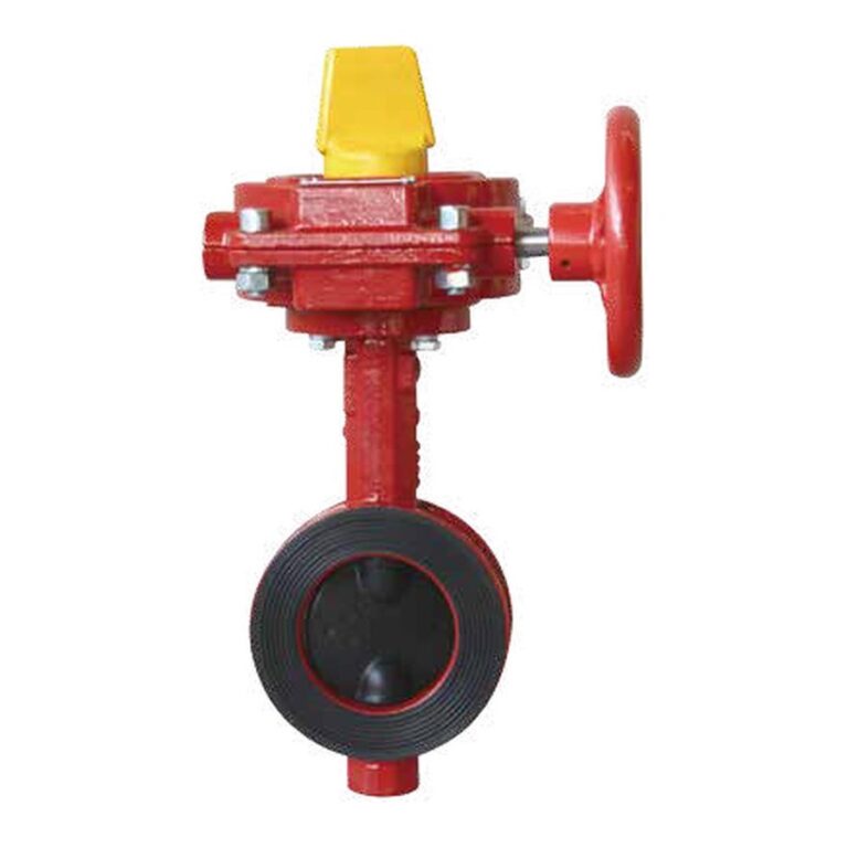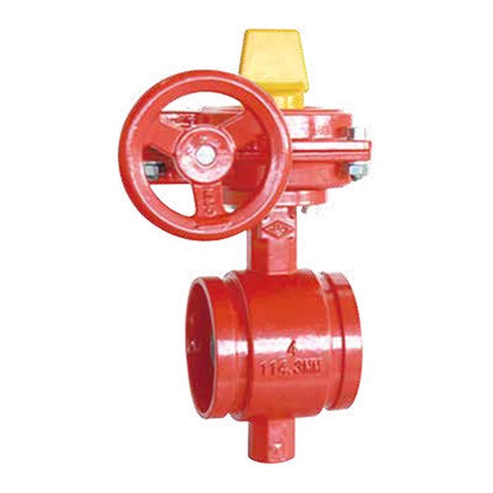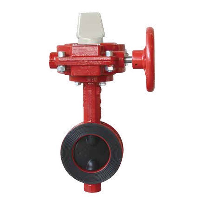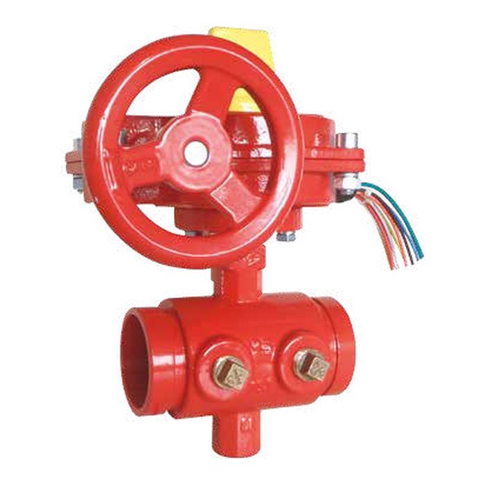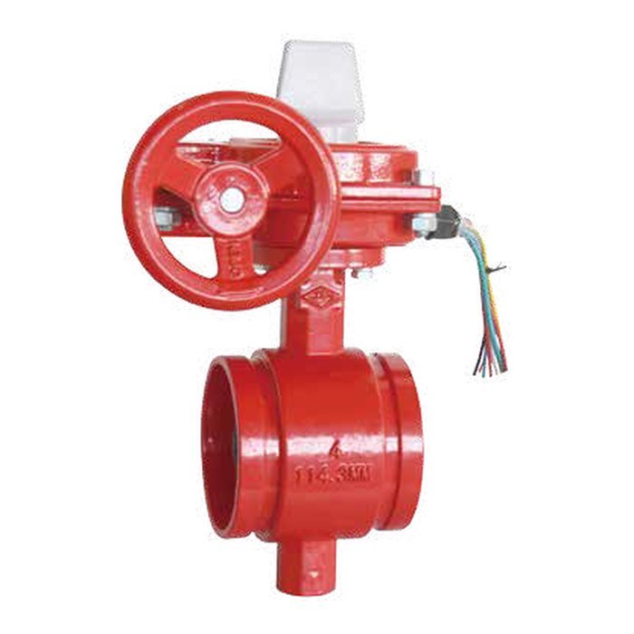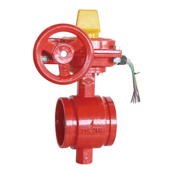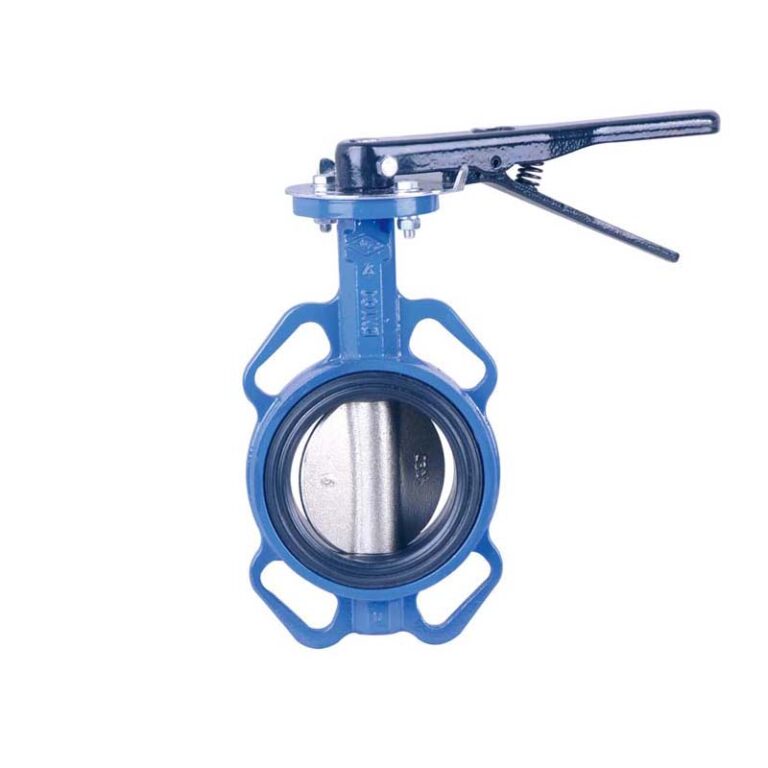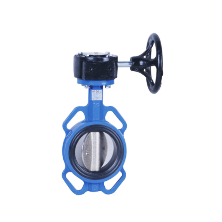
A butterfly valve opens and closes the line by turning a disc inside the body through a quarter turn. In fire systems it is widely used as an indicating control valve in place of a gate valve, because it is lighter, shorter and quick to install. This guide explains when to choose it, wafer versus grooved, and the role of the supervisory switch.
Key points
- Much shorter and lighter than a gate valve of the same size.
- In fire systems it is used with an indicating gear operator and a tamper switch that signals when the valve is moved.
- Ends: wafer between flanges, or grooved with grooved couplings.
- The disc protrudes into the pipe when open, so check clearance with adjacent fittings.
How does it work?
The disc is mounted on a stem through the centre of the body. Turning the stem 90 degrees sets the disc parallel to the flow and opens the line; turning it back sets it across the flow and closes it. On fire valves the stem is turned through a gear operator with a handwheel, which slows closing and shows the valve position on an indicator.
Why the tamper switch matters
NFPA 13 requires control valves to be indicating and supervised in the open position. The tamper switch built into the gear operator signals the alarm panel as soon as the valve leaves the fully open position, so no valve stays closed by mistake unnoticed.
Normally open or normally closed switch?
Models with a normally closed switch are available to match the alarm panel circuit on the project. Choose the type the fire alarm designer specifies.
Wafer or grooved?
| Item | Wafer | Grooved |
|---|---|---|
| Installation | Between two flanges with long bolts | With two grooved couplings |
| Weight and length | Light and short | Light, and quicker to install |
| Best for | Flanged lines | Grooved systems |
| Removal | Flange bolts must be undone | Undo two couplings |
MECH models
| Model | Type | Sizes | Working pressure | Approval |
|---|---|---|---|---|
| XD381X | Grooved with tamper switch | 2″ – 12″ | 300 / 363 PSI | UL / FM / VdS |
| D381X | Grooved | 2″ – 12″ | By version, up to 363 psig | UL / FM |
| D371X | Wafer | 2″ – 12″ | By version, up to 363 psig | UL / FM |
| XD371XG / XD381XG | Wafer / grooved, normally closed switch | 2″ – 12″ | 300 – 363 PSI | UL |
| D371X205 | Wafer for water networks | 2″ – 24″ | 300 PSI | — |
| D71X4 | Flanged, lever | 1-1/2″ – 32″ | 300 PSI | — |
The models are designed to MSS SP-67, with grooved ends to AWWA C606.
Installation points
- Check disc clearance: when open the disc projects beyond the body, so do not fit the valve hard against a fitting that blocks it without checking the data sheet.
- Install with the disc almost closed to protect its edge, then open it once the joints are tight.
- Connect the tamper switch to the alarm panel and test the signal before commissioning.
- Make sure the position indicator is visible from the operating point.
Frequently asked questions
Is a butterfly valve acceptable as a sprinkler control valve?
Yes, provided it is listed for fire protection service, indicating and supervised, and accepted by the project consultant.
Can the lever model be used in a fire system?
Fire system control valves must be listed, indicating and supervised. Models intended for water networks without UL / FM approval are not for that use.
Why a gear operator rather than a lever?
The gear operator makes closing gradual, reducing the risk of water hammer, and provides a clear indicator and a place for the tamper switch.
References
- NFPA 13 — Standard for the Installation of Sprinkler Systems.
- UL 1091 — Butterfly Valves for Fire-Protection Service.
- FM Class 1112 — Indicating Valves (Butterfly or Ball Type).
- MSS SP-67 — Butterfly Valves.
- AWWA C606 — Grooved and Shouldered Joints.
This guide is for technical awareness and does not replace the manufacturer’s data sheet or the requirements of the project’s approved designer.