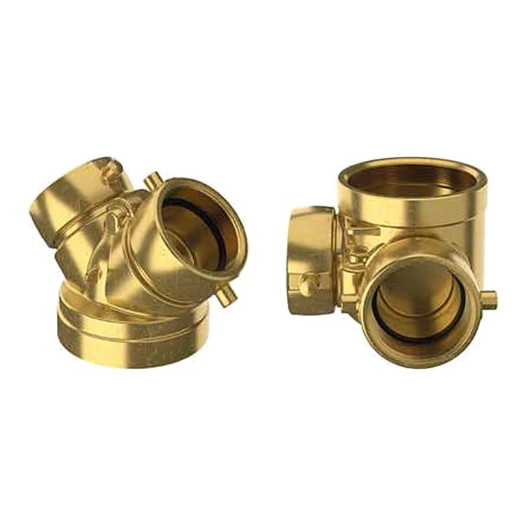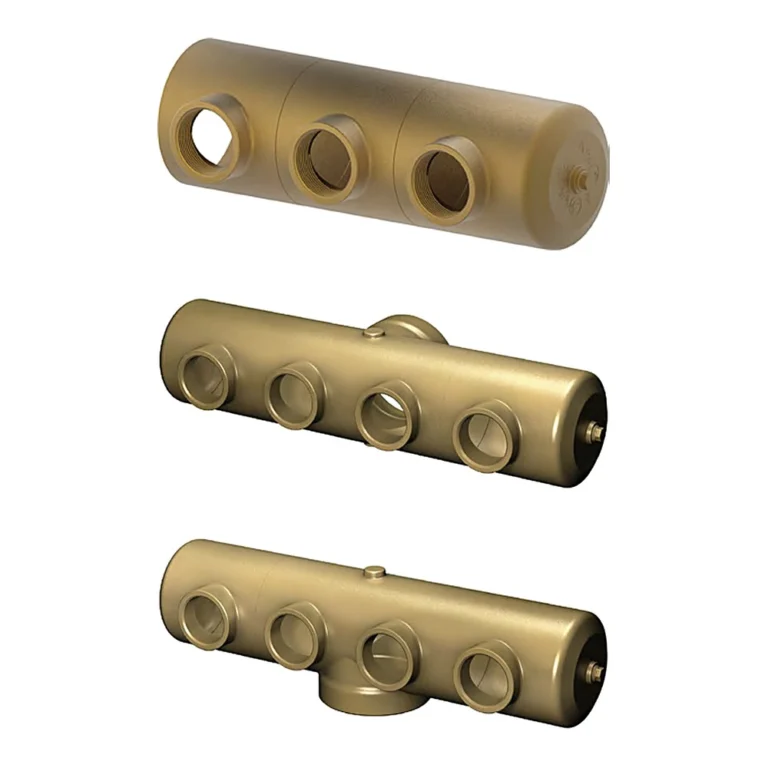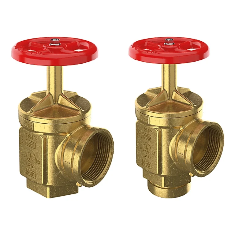
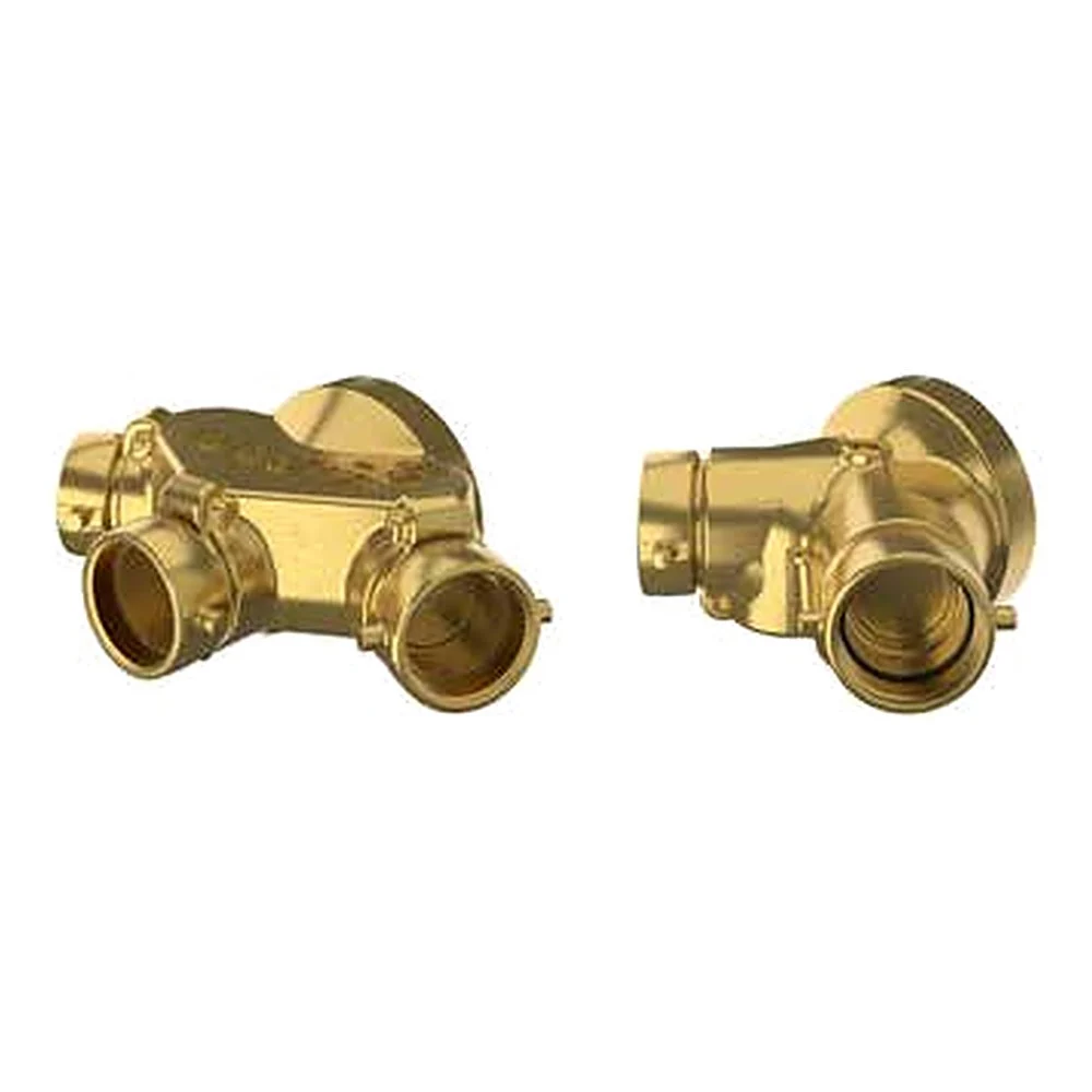
The GIACOMINI A105 is an exposed fire department connection with an independent drop clapper on each inlet, in two-way or three-way bodies. It is used as an auxiliary inlet providing 500 GPM minimum to supplement the fire protection water supply; the swing clapper gives a full waterway. Available with a 4″ or 6″ outlet, threaded or grooved.
In short
- Two-way double clapper, or three-way triple clapper.
- Inlets 2-1/2″ or 3″; outlet 4″ or 6″.
- Rated pressure 300 psi.
- Cast brass body, pin lug hose thread swivels, straight NPT outlet.
- Branding: A105/1 = AUTO-SPKR, A105/2 = STANDPIPE, A105/3 = plain.
- Approval varies by size (shown in the technical data table).
How the connection works
Each inlet has its own clapper that opens under pressure from the fire department hose and stays closed on unused inlets, so hoses can be connected one after another while the line is charged.
The three-way body is used where the system demand is higher; the number of inlets is set by the project designer from the system demand.
Related items
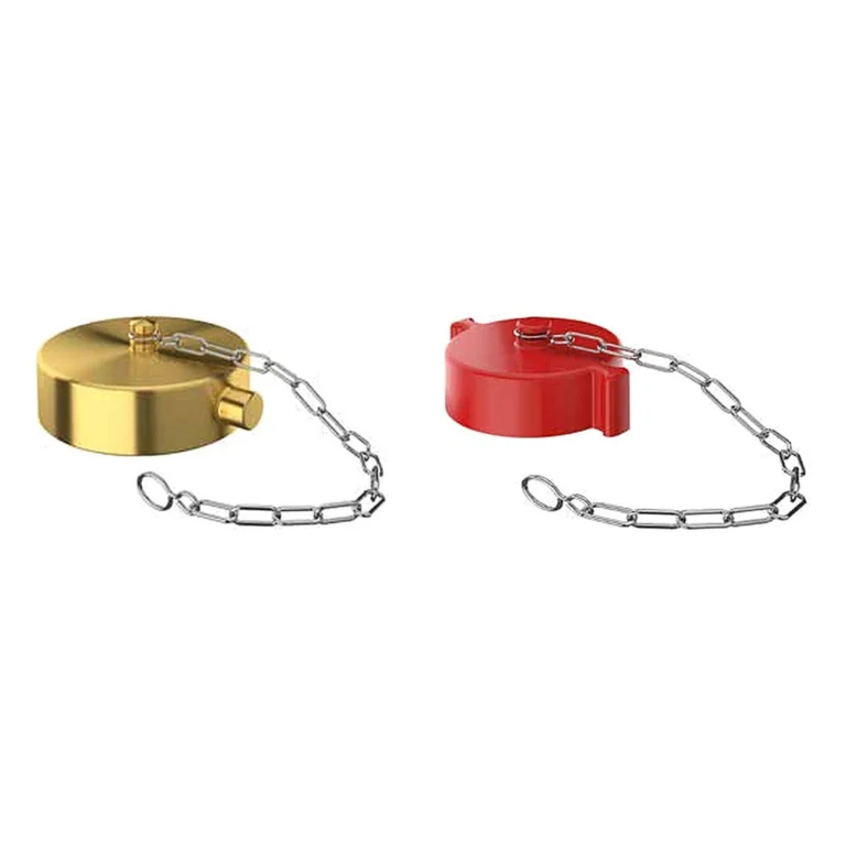
- A81 plug and chain for the inlets (per the catalogue).
Technical data
| Item | Value |
|---|---|
| Model | A105 |
| Rated pressure | 300 psi |
| Flow | 500 GPM minimum |
| Body | Cast brass |
| 4″ × 2-1/2″, 2-way, groove | A 9-13/32″ · B 13-9/32″ · C 5-1/32″ |
| 6″ × 2-1/2″, 2-way, groove | A 9-17/64″ · B 15-13/64″ · C 7-3/32″ |
| 4″ × 2-1/2″, 2-way, thread | A 7-9/32″ · B 11-21/32″ · C 5-1/32″ — FM · UL 175 psi |
| 4″ × 3″, 2-way, thread | A 8-1/32″ · B 12-7/8″ · C 5-1/32″ — UL 300 psi |
| 6″ × 2-1/2″, 2-way, thread | A 8-5/32″ · B 11-21/32″ · C 7-3/32″ — UL 175 psi |
| 6″ × 3″, 2-way, thread | A 8-3/4″ · B 12-7/8″ · C 7-15/32″ — UL 300 psi |
| 4″ × 2-1/2″, 3-way, thread | A 9-1/4″ · B 15-3/16″ · C 7-3/32″ |
| 6″ × 2-1/2″, 3-way, thread | A 9-1/4″ · B 15-3/16″ · C 7-3/32″ |
The critical point: approval depends on size
Not every A105 size carries the same approval. Per the catalogue page: threaded two-way 4″ × 2-1/2″ is FM Approved and UL Listed at 175 psi; 4″ × 3″ and 6″ × 3″ are UL Listed at 300 psi; 6″ × 2-1/2″ is UL Listed at 175 psi. Grooved and three-way versions show no approval mark in the catalogue. Where the project requires an approval, pick an approved size.
State the branding (AUTO-SPKR, STANDPIPE or plain) and inlet thread when ordering.
General design notes for the fire department connection
- Location: on the street side of the building, visible and accessible to the fire apparatus, as agreed with the fire department.
- Height: the inlets are typically between 18 and 48 in (457 – 1219 mm) above the adjoining grade per NFPA 14.
- A listed check valve is installed in the connection line, and no shut-off valve is placed between the connection and the system.
- The sign shows which system the connection feeds (AUTO SPKR or STANDPIPE), and the inlets are fitted with caps or plugs.
- The inlet thread matches the local fire department’s hose thread.
General engineering notes
These points are general principles from the NFPA standards named and common design practice, not from the GIACOMINI datasheet. The final decision rests with the project’s approved designer per the adopted edition of the standard and the authority having jurisdiction.
Installation steps
- Agree the location and height with the fire department before installation.
- Connect the outlet to the supply line, with a listed check valve in the line.
- Check the clappers move freely and the inlet thread matches the fire department hoses.
- Fit the inlet caps or plugs and the identification sign, then pressure test the line.
Common mistakes
- Inlet thread that does not match the local fire department hoses.
- Installing a shut-off valve between the connection and the system.
- A connection hidden behind planting or parked cars.
- Leaving inlets uncapped so debris gets in and jams the clappers.
Inspection and maintenance
Inspect periodically per NFPA 25: visible and accessible, caps in place, swivels rotating freely, clappers sound, and the sign in place.
Inspection, testing and maintenance are the owner’s responsibility per NFPA 25 and the authority having jurisdiction, preferably by a qualified company. Notify the owner, the monitoring station and everyone affected before any test.
Files and ordering
The GIACOMINI catalogue page for the A105 and the UL and FM listings are in the files section of this page. When ordering, state the size, number of ways, outlet type (thread or groove), branding and inlet thread.
How to order
Use the “Build your order” section on this page: add every model and quantity, then send the whole order by email or WhatsApp. It reaches us as a tidy PDF request sheet and we contact you with the quotation.
FAQ
A105 vs A95?
The A105 has a clapper per inlet, more sizes and a three-way option; the A95 has one clapper and one size.
Which branding?
AUTO-SPKR for a connection feeding sprinklers, STANDPIPE for standpipes, and plain with a separate sign for a combined system.
References
- GIACOMINI A105 — Datasheet (attached)
- NFPA 14 — Standard for the Installation of Standpipe and Hose Systems
- NFPA 13 — Standard for the Installation of Sprinkler Systems
- NFPA 25 — Inspection, Testing and Maintenance of Water-Based Fire Protection Systems
This page is general information to help with selection and ordering, taken from the attached GIACOMINI datasheet. Final design is set by the project’s approved designer; the project specification, the consultant’s drawings and the latest datasheet revision govern.