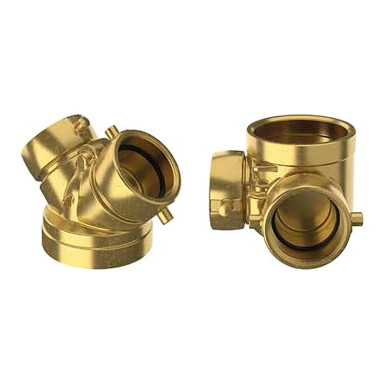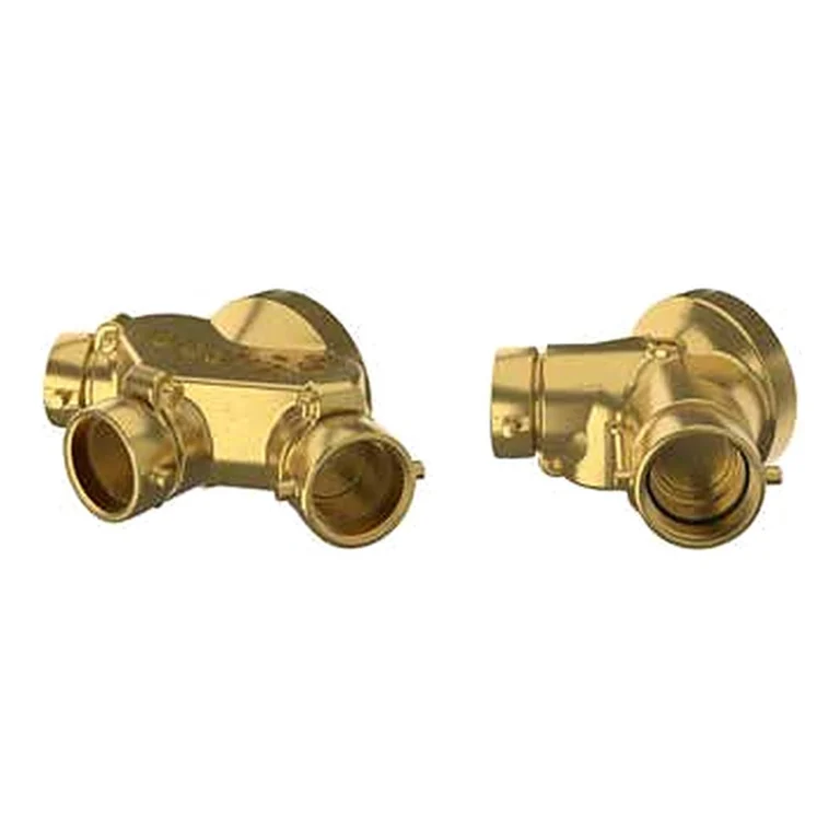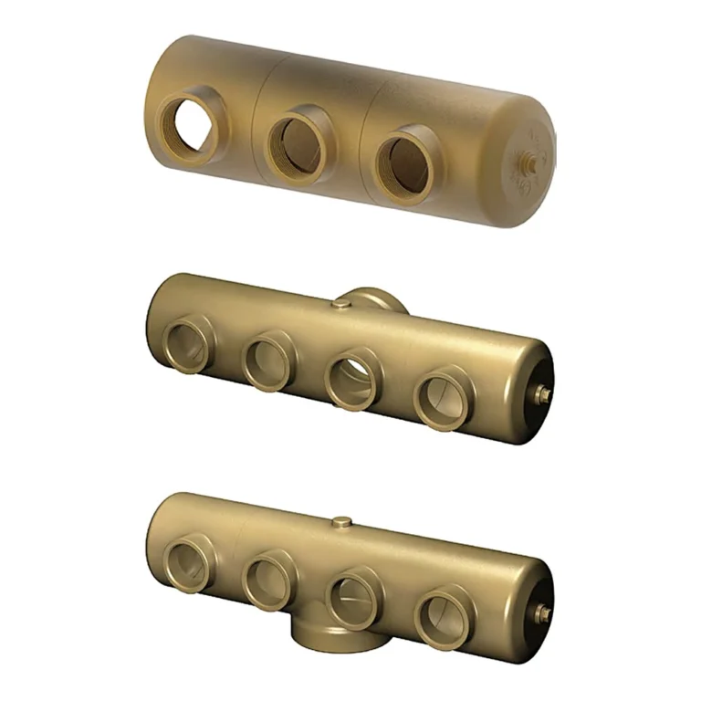
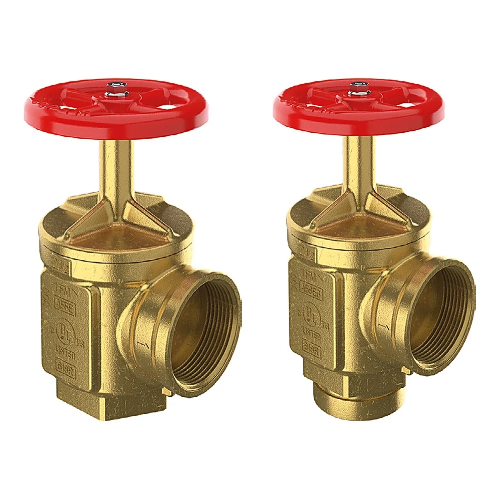
GIACOMINI angle hose valves (datasheet 1043EN) are forged brass 90° pattern valves, with threaded or grooved connections, that control water flow from the main risers in standpipe systems. They are used with a fire hose rack assembly in cabinets, or as fire department outlet connections. The series has four models that differ in inlet and outlet type, all rated 300 psi. See the guide to types of fire fighting valves.
In short
- Models: A55E · A56E · A55EG · A56EG.
- Sizes: 1-1/2″ and 2-1/2″ (grooved models 2-1/2″ only).
- Rated pressure 300 psi (20.6 bar).
- Forged brass body and stopper; red painted aluminium handwheel.
- FM Approved, UL and ULC Listed.
How the valve works
Turning the handwheel counter-clockwise opens the valve and lets water flow out; turning it clockwise shuts it off.
The models differ in connections: the A55E has a female NPT outlet for a nipple or adapter, and the A56E a male hose thread outlet for a hose or cap directly. Models ending in G have a grooved inlet for coupling to grooved pipe.
Related items
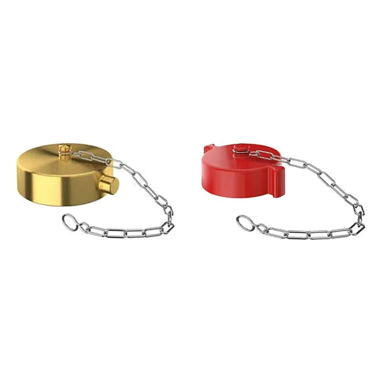
- A80 cap and chain to protect the A56E outlet thread.
- A155 / A156 pressure restricting valves where outlet pressure is too high.
Technical data
| Item | Value |
|---|---|
| Models | A55E · A56E · A55EG · A56EG |
| Rated pressure | 300 psi (20.6 bar) |
| Body and stopper | Forged brass CuZn40Pb2 to EN 12165 CW617N (similar to ASTM B124 C37700) |
| Stem | Brass EN 12164 CW617N for 1-1/2″; CW713R for 2-1/2″ |
| Handwheel | Red painted aluminium |
| A55E 1-1/2″ dimensions | A 4-1/32″ · B 7-19/32″ · C 2-5/32″ · D 1-7/8″ · E 3-11/16″ |
| A55E 2-1/2″ dimensions | A 5-1/8″ · B 10-19/32″ · C 3-5/32″ · D 2-5/8″ · E 5-11/32″ |
| A56E 1-1/2″ dimensions | A 4-1/32″ · B 7-19/32″ · C 2-1/4″ · D 1-7/8″ · E 3-13/16″ |
| A56E 2-1/2″ dimensions | A 5-1/8″ · B 10-19/32″ · C 3-3/16″ · D 2-5/8″ · E 5-3/8″ |
| A55EG 2-1/2″ dimensions | A 5-1/8″ · B 11-3/16″ · C 3-5/32″ · D 3-9/16″ · E 5-11/32″ |
| A56EG 2-1/2″ dimensions | A 5-1/8″ · B 11-3/16″ · C 3-3/16″ · D 3-9/16″ · E 5-3/8″ |
| Approvals | UL (EX2964), ULC, FM (1521/1522) |
The critical point: outlet pressure and hose thread
This is a standard valve and does not reduce pressure. If outlet pressure is above what the hose allows, use the A155 / A156 pressure restricting valve or a pressure regulating device per the project design.
The A56E outlet is a hose thread; state the type when ordering so it matches the local fire department hoses.
General design notes for standpipe systems
- System classes in NFPA 14: Class I has 2-1/2″ outlets for fire fighters, Class II has 1-1/2″ hose stations for occupants, and Class III combines both.
- Required residual pressure at the hydraulically most remote outlet: 100 psi for a 2-1/2″ connection and 65 psi for a 1-1/2″ station, as the Giacomini datasheet quotes from NFPA 14.
- Where pressure at a hose outlet exceeds 175 psi an appropriate pressure regulating device is used, as the FM Approval Guide states for hose valves.
- The hose outlet thread (NH/NST or other) must match the local fire department’s hose thread; confirm before ordering.
General engineering notes
These points are general principles from the NFPA standards named and common design practice, not from the GIACOMINI datasheet. The final decision rests with the project’s approved designer per the adopted edition of the standard and the authority having jurisdiction.
Installation steps
- Check size and thread or groove type against the supply line.
- Apply sealant to the pipe thread only, and tighten with a wrench on the hexagon at the bottom of the body, never on the handwheel or bonnet.
- Orient the outlet inside the cabinet so the hose pulls out without kinking.
- Fit the cap or hose, then pressure test for tightness and open and close the valve to check it moves freely.
Common mistakes
- Tightening on the bonnet or handwheel instead of the lower hexagon, distorting the valve.
- Ordering without stating the hose thread, so the fire department hose does not fit.
- Fitting a standard valve on floors where pressure is too high, with no regulating device.
- Leaving the outlet without a cap so dirt builds up on the thread.
Inspection and maintenance
Inspect periodically for cap, handwheel, leaks and corrosion, and operate the valve to check movement, per the NFPA 25 schedules.
Inspection, testing and maintenance are the owner’s responsibility per NFPA 25 and the authority having jurisdiction, preferably by a qualified company. Notify the owner, the monitoring station and everyone affected before any test.
Files and ordering
The GIACOMINI datasheet 1043EN and the UL and FM listings are in the files section of this page. When ordering, state the model, size, outlet thread type and finish.
How to order
Use the “Build your order” section on this page: add every model and quantity, then send the whole order by email or WhatsApp. It reaches us as a tidy PDF request sheet and we contact you with the quotation.
FAQ
What is the difference between A55E and A56E?
The A55E has a female NPT outlet; the A56E has a male hose thread outlet that takes the hose directly.
When do I choose the grooved model?
When the riser pipework is grooved: the A55EG or A56EG is fitted with a coupling, in 2-1/2″ only.
Does the valve reduce pressure?
No. For pressure restriction use the A155 / A156.
References
- GIACOMINI 1043EN — Datasheet (attached)
- NFPA 14 — Standard for the Installation of Standpipe and Hose Systems
- NFPA 25 — Inspection, Testing and Maintenance of Water-Based Fire Protection Systems
This page is general information to help with selection and ordering, taken from the attached GIACOMINI datasheet. Final design is set by the project’s approved designer; the project specification, the consultant’s drawings and the latest datasheet revision govern.