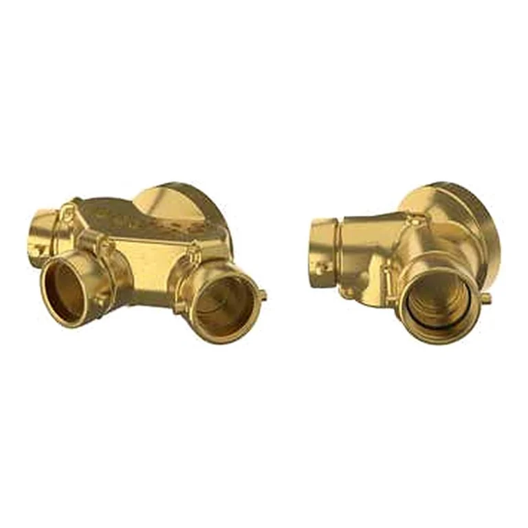
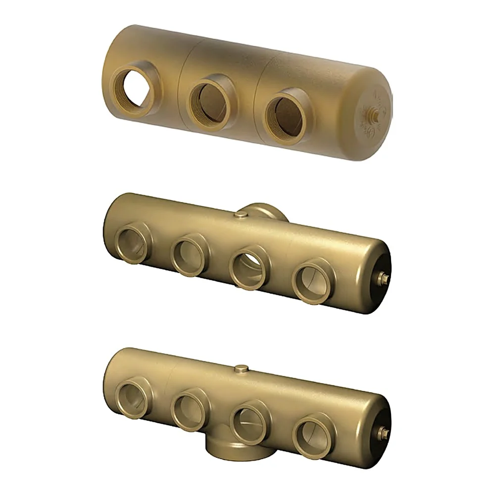
The GIACOMINI A111, A112 and A113 series (datasheet 0724EN) are forged brass multi-inlet connection bodies, with three, four or six 3″ inlets and a 6″ or 8″ outlet. They serve three uses: a flush fire department inlet connection supplementing the system water supply, a roof outlet manifold for Class I and Class III service, or a fire pump test header. The bodies have no clappers; when used as an inlet, A91C clapper snoots are required.
In short
- A111 end outlet, A112 back outlet, A113 angle outlet.
- 3″ female NPT inlets: 3 / 4 / 6 on A111; 4 / 6 on A112 and A113.
- 6″ female NPT outlet; the 8″ size is the 6″ body with a 6″ × 8″ adapter.
- Rated pressure 300 psi (20.6 bar); rough brass finish.
- A111 6″ × 3″ with 3 and 4 inlets is UL Listed as both roof manifold and fire department connection.
The three uses
Fire department inlet: A91C clapper snoots are fitted to the inlets, and the fire department pumps into the system through several hoses.
Roof outlet manifold: for Class I and Class III service, as a water source for fire fighting. Each outlet must supply a minimum of 250 GPM and is controlled by an angle or straight hose valve, attached directly or installed remotely.
Pump test header: every fire pump needs a way to verify it works; a test header lets large quantities of water flow through multiple hoses to measure pump performance.
Related items
- A91C clapper snoots for the inlets when used as a fire department connection (UL Listed under EX3314).
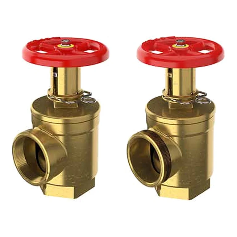
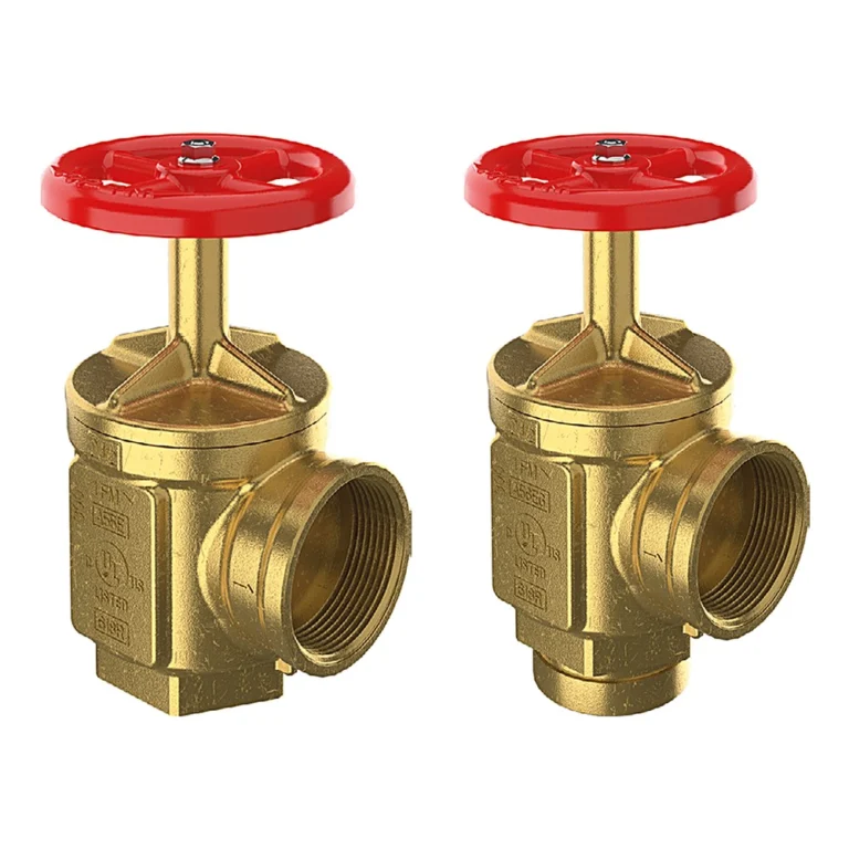
- A55E / A56E hose valves when used as an outlet manifold or test header.
Technical data
| Item | Value |
|---|---|
| Models | A111 · A112 · A113 |
| Rated pressure | 300 psi (20.6 bar) |
| Body | Forged brass CuZn40Pb2 to EN 12165 CW617N (similar to ASTM B124 C37700) |
| Finish | Rough brass |
| A111 6″ × 3″ /3 | A 23-23/64″ · B 8-11/32″ · C 7-21/64″ · D 7″ |
| A111 6″ × 3″ /4 | A 30-23/64″ · B 8-11/32″ · C 7-21/64″ · D 7″ |
| A111 6″ × 3″ /6 | A 44-23/64″ · B 8-11/32″ · C 7-21/64″ · D 7″ |
| A112 6″ × 3″ /4 | A 32-7/32″ · B 9-13/32″ · C 7-21/64″ · D 7″ · E 7-31/64″ |
| A112 6″ × 3″ /6 | A 46-7/32″ · B 9-13/32″ · C 7-21/64″ · D 7″ · E 7-31/64″ |
| A113 6″ × 3″ /4 | A 32-7/32″ · B 8-25/32″ · C 7-21/64″ · D 7″ · E 7-31/64″ · F 8-13/16″ |
| A113 6″ × 3″ /6 | A 46-7/32″ · B 8-25/32″ · C 7-21/64″ · D 7″ · E 7-31/64″ · F 8-13/16″ |
| Approval | A111 6″ × 3″ with 3 and 4 inlets: UL Listed 300 psi. Other sizes show no approval mark in the datasheet. |
The critical point: the body has no clappers
The body has no clappers. When used as a fire department connection, A91C clapper snoots must be ordered and fitted to every inlet; otherwise water escapes from unused inlets.
The listing covers only the A111 6″ × 3″ with 3 and 4 inlets. Where the project requires UL, do not substitute another model or size without checking.
General design notes for the fire department connection
- Location: on the street side of the building, visible and accessible to the fire apparatus, as agreed with the fire department.
- Height: the inlets are typically between 18 and 48 in (457 – 1219 mm) above the adjoining grade per NFPA 14.
- A listed check valve is installed in the connection line, and no shut-off valve is placed between the connection and the system.
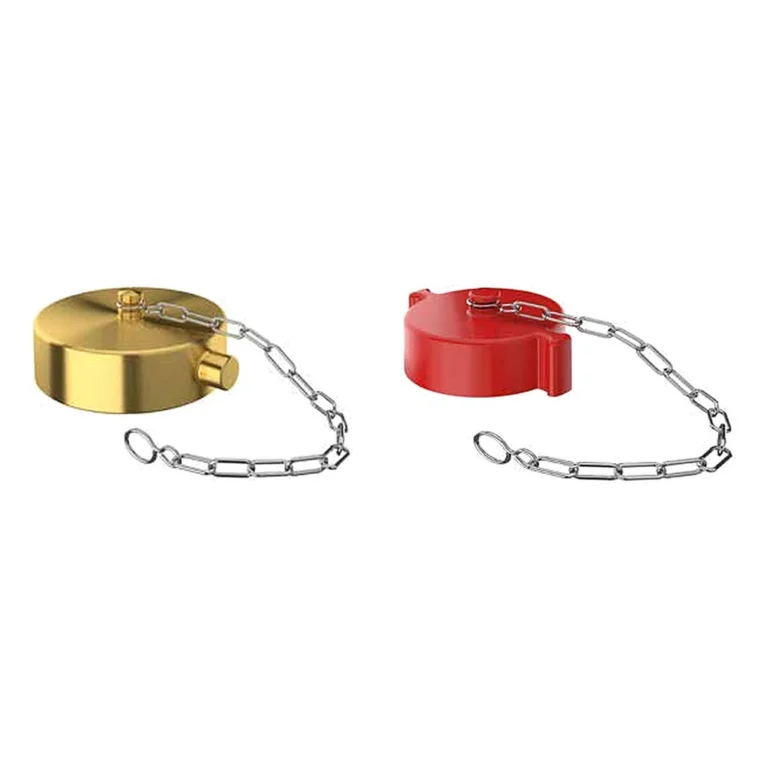
- The sign shows which system the connection feeds (AUTO SPKR or STANDPIPE), and the inlets are fitted with caps or plugs.
- The inlet thread matches the local fire department’s hose thread.
General engineering notes
These points are general principles from the NFPA standards named and common design practice, not from the GIACOMINI datasheet. The final decision rests with the project’s approved designer per the adopted edition of the standard and the authority having jurisdiction.
Installation steps
- Confirm the use (inlet, roof manifold, test header), number of inlets and outlet direction with the project designer.
- Connect the body outlet to the 6″ line, or through the 6″ × 8″ adapter.
- Fit the inlets with A91C clapper snoots (inlet use) or hose valves (outlet or test header use).
- Fit the wall plate, caps and identification sign, then pressure test.
Common mistakes
- Using the body as an inlet without A91C clapper snoots.
- Fewer inlets than the system demand or pump test needs.
- A test header with no control valves on the outlets.
- Thread that does not match the fire department hoses.
Inspection and maintenance
Inspect periodically per NFPA 25: visible and accessible, caps in place, swivels rotating freely, clappers sound, and the sign in place.
Inspection, testing and maintenance are the owner’s responsibility per NFPA 25 and the authority having jurisdiction, preferably by a qualified company. Notify the owner, the monitoring station and everyone affected before any test.
Files and ordering
The GIACOMINI datasheet 0724EN and the UL listing are in the files section of this page. When ordering, state the model, size, number of inlets, the use, and whether A91C clapper snoots are needed.
How to order
Use the “Build your order” section on this page: add every model and quantity, then send the whole order by email or WhatsApp. It reaches us as a tidy PDF request sheet and we contact you with the quotation.
FAQ
How do the three models differ?
Only in outlet direction: end on the A111, back on the A112, angle on the A113.
How many outlets for a pump test header?
The project designer sets it from the pump capacity per NFPA 20.
Is the 8″ a different body?
No, it is the 6″ body with a 6″ × 8″ adapter.
References
- GIACOMINI 0724EN — Datasheet (attached)
- NFPA 14 — Standard for the Installation of Standpipe and Hose Systems
- NFPA 20 — Standard for the Installation of Stationary Pumps for Fire Protection
- NFPA 25 — Inspection, Testing and Maintenance of Water-Based Fire Protection Systems
This page is general information to help with selection and ordering, taken from the attached GIACOMINI datasheet. Final design is set by the project’s approved designer; the project specification, the consultant’s drawings and the latest datasheet revision govern.