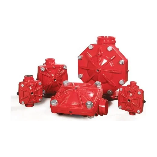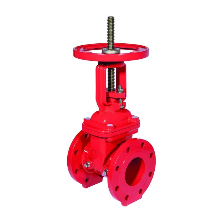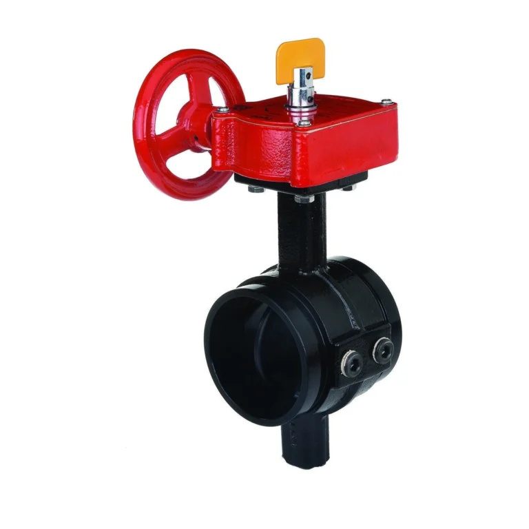
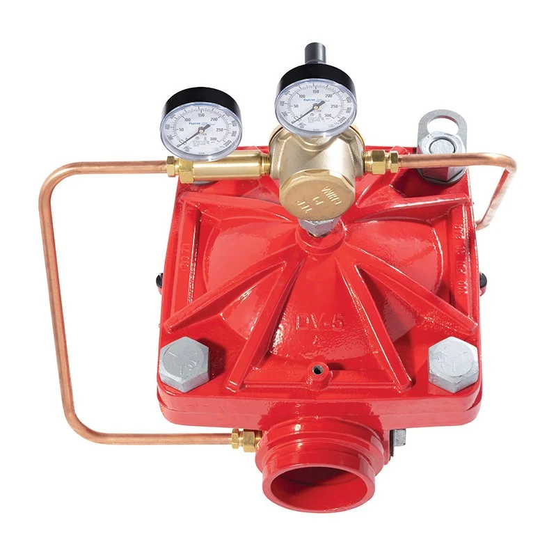
The TYCO PRV-1A is a factory-assembled, fully trimmed pilot-operated pressure reducing valve, 2″ to 8″. It is used on water-filled pipes to reduce a higher inlet pressure to a lower delivery pressure under static and flowing conditions, holding the outlet set pressure within a close range regardless of inlet or flow changes. It uses the DV-5A diaphragm valve body. See the guide to types of fire fighting valves.
In short
- Sizes 2″ – 8″ (DN50 – DN200), flange × flange or groove × groove.
- Factory outlet set about 125 psi (8.6 bar), field adjustable 90 – 175 psi.
- Maximum inlet pressure by size (e.g. 250 psi for 2″, 300 psi for 4″).
- Installed in the main header feeding system risers or standpipes, or within a floor control assembly.
- Approvals: UL and C-UL (2″ – 6″ only) and FM.
How the valve works
Inlet pressure enters the diaphragm chamber through a strainer. Flow out of the chamber through the pilot valve is controlled by a spring set to the required outlet pressure, with a sensing line connecting the pilot to the piping downstream.
If downstream pressure rises above set, flow out of the chamber stops, chamber pressure rises and the valve throttles; if it falls, flow out increases and the valve opens further, keeping outlet pressure steady.
Technical data
| Item | Value |
|---|---|
| Type | Pilot-operated diaphragm pressure reducing |
| Sizes | 2″ – 8″ (DN50 – DN200) |
| End connections | Flange × flange or groove × groove |
| Outlet set pressure | 90 – 175 psi (6.2 – 12.1 bar) |
| Materials | Epoxy-coated ductile iron body and cover, fabric-reinforced Teflon-coated EPDM diaphragm |
| Approvals | UL · C-UL (2″ – 6″) · FM |
The critical point: field setting and testing
The UL listing is based on field setting to the required outlet pressures and flows, testing after installation per NFPA 13 and/or NFPA 14, and inspection per NFPA 25, with the 3/4″ CLA-VAL 55L-60 relief valve.
Installation steps
- Install the valve with the flow arrow on the diaphragm cover pointing in the direction of flow, and flush the pipe lines of chips and scale before installing.
- Do not lift the valve by its trim, and take care not to damage the trim during installation.
- Install in the main header or floor control assembly per the datasheet figures.
- Field-set the outlet pressure within 90 – 175 psi, then flow test per the standard.
Common mistakes
- Installing against the flow arrow.
- Leaving the factory setting instead of setting the project’s required pressure.
- Not flushing the lines first, clogging the strainer or pilot.
Inspection and maintenance
Before closing a main control valve for maintenance, obtain permission from the proper authorities and notify everyone affected. The owner is responsible for inspection, testing and maintenance to NFPA 25 and the authority having jurisdiction; any impairment must be corrected immediately.
Periodic flow tests of pressure reducing valves are done per NFPA 25, and the inlet strainer is cleaned.
Files and ordering
TYCO datasheet TFP1581 and the available approval certificates are in the files section of this page. When ordering, state the size, end connections and required outlet pressure. The datasheet lists the part numbers (P/N).
How to order
Use the “Build your order” section on this page: add every model and quantity, then send the whole order by email or WhatsApp. It reaches us as a tidy PDF request sheet and we contact you with the quotation.
FAQ
Where is a pressure reducing valve installed?
Where supply pressure exceeds what the system or hose outlets allow, such as lower floors of tall buildings, in the main header or floor control assembly.
Does the diaphragm chamber need bleeding?
No, the datasheet states the design eliminates the need to bleed trapped air from the diaphragm chamber.
What is the outlet set range?
90 – 175 psi, with a factory setting of about 125 psi.
References
- TYCO TFP1581 — Datasheet (attached)
- NFPA 14 — Standpipe and Hose Systems
- NFPA 13 — Standard for the Installation of Sprinkler Systems
- NFPA 25 — Inspection, Testing and Maintenance of Water-Based Fire Protection Systems
This page is general information to help with selection and ordering, taken from the attached TYCO datasheet. Final design is set by the project’s approved designer; the project specification, the consultant’s drawings and the latest datasheet revision govern.