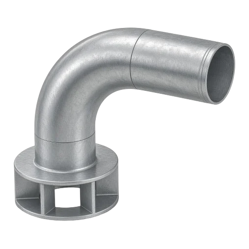
The Fu-Mech grooved anti-vortex plate (model FU-AVXG) is fitted to the suction or outlet pipe inside a tank to break up the vortex that forms as water is drawn off — keeping air out of the pump and the flow steady. This guide explains why vortices form, the role of the plate in fire tanks, the differences between types and how to order.
At a glance
- Prevents air entrainment at the suction.
- Protects pumps from cavitation.
- Uses more of the tank’s stored volume.
- Joins the suction pipe with a grooved coupling: quick to fit and easy to remove.
Why does a vortex form?
When a pump draws water from a tank outlet, the water above the outlet starts to rotate. As the water level over the outlet falls, the vortex strengthens until an air core reaches the suction opening and air is drawn into the pump with the water.
Air in the suction line reduces the water the pump actually delivers, causes cavitation, vibration and noise, and can damage pump parts over time. In fire systems it means the pump may not deliver its required duty when it is needed.
How does an anti-vortex plate work?
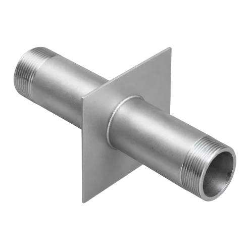
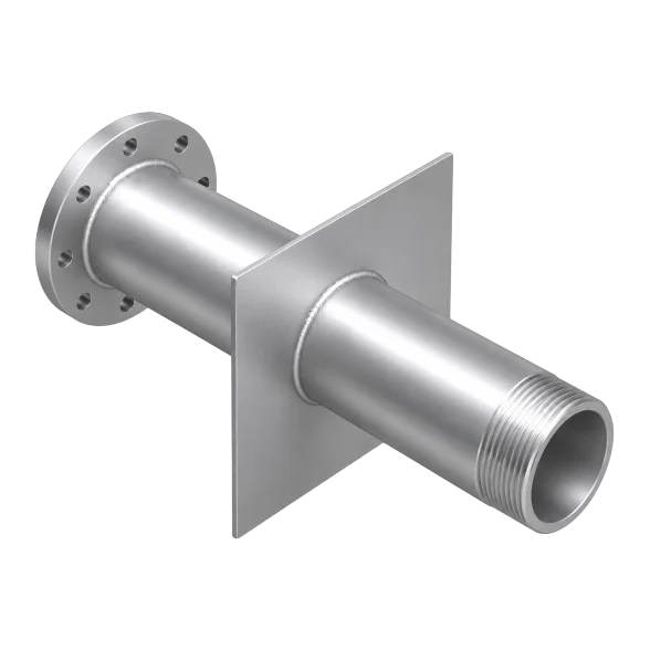
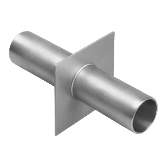
The plate is fitted on the suction outlet inside the tank. It breaks up the rotation of the water above the opening and stops the air core forming. The result is steady, air-free flow, and the pump can draw the tank down further before air gets in — more usable volume.
Fire-pump suction tanks
Anti-vortex plates are a recognised part of fire-pump suction connections from tanks in NFPA standards (such as NFPA 22 for tanks and NFPA 20 for pumps). Plate size and its distance from the tank floor are set by the project’s approved designer to the applicable standard.
Tip
Send us the consultant’s drawing if it fixes the plate dimensions or level, and we fabricate the plate to it.
Types and codes
| Type | Connection | Code | Use when |
|---|---|---|---|
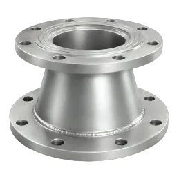
| Flanged | Flange | FU-AVXA / FU-AVXP | Tank outlet or suction line is flanged |
| Grooved — this product | Grooved end | FU-AVXG | Suction pipework is grooved |
Where it is used
- Fire-fighting water tanks — fire-pump suction outlets.
- Domestic and irrigation water tanks.
- Ground reservoirs and sumps feeding pumps.
Common mistakes
- Leaving a suction outlet without an anti-vortex plate in a tank that is drawn down low.
- Fitting it at a level or size different from the approved drawing.
- Choosing a connection that does not match the suction line (flanged versus grooved).
How to order
Use the “Build your order” section on this page: add every model, size and quantity, then send the whole order by email or WhatsApp. It reaches us as a tidy PDF request sheet and we contact you with the quotation.
- Model code FU-AVXG
- Suction pipe size (DN)
- Quantity
- The consultant’s drawing, if it sets plate dimensions
Frequently asked questions
What does an anti-vortex plate do in a fire tank?
It stops a vortex forming at the suction outlet, so no air is drawn into the pump. Air in the suction line causes cavitation, vibration and loss of pump performance; the plate also lets the pump draw the tank down further, using more of its stored volume.
Do fire-protection standards call for it?
Anti-vortex plates are a recognised part of fire-pump suction connections from tanks in NFPA standards such as NFPA 22 and NFPA 20. The project’s approved designer sets its size and level to the applicable standard.
What is the difference between the flanged and grooved types?
Same function; the difference is how it joins the suction pipe: flanged (FU-AVXA / FU-AVXP) for flanged lines, grooved end (FU-AVXG) for grooved networks.
What should I send for a quotation?
Model code, suction pipe size (DN), quantity. If the consultant’s drawing gives plate dimensions, attach the drawing.
References
- NFPA 22 — Standard for Water Tanks for Private Fire Protection
- NFPA 20 — Standard for the Installation of Stationary Pumps for Fire Protection
- AWWA C606 — Grooved and Shouldered Joints
- Fu-Mech catalogue — Edition 08/2026
This guide is general information to help with selection and ordering. Final design, sizes and positions are set by the project’s approved designer; the project specification and the consultant’s drawings govern. Specifications may vary by project; datasheets and drawings are available on request.