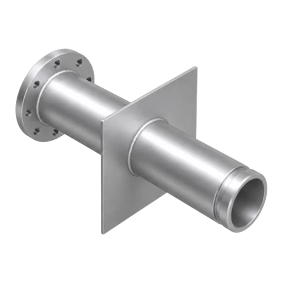
 Flanged × grooved end
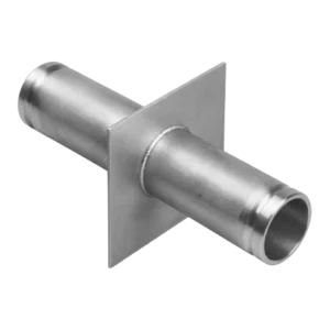
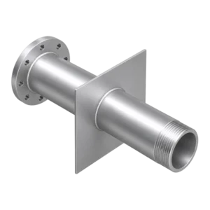
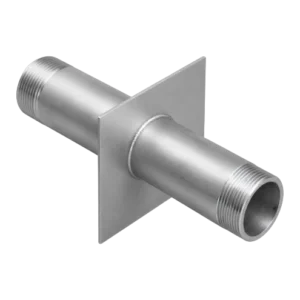
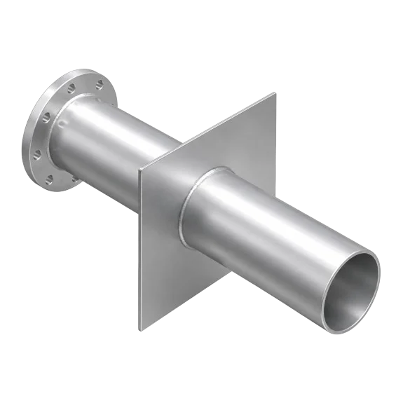
The Fu-Mech flanged × grooved end puddle flange (model FU-1SGA (ANSI) and FU-1SGP (PN16)) is a pipe section with a steel plate welded around it, cast into a concrete wall or slab to stop water tracking along the pipe surface where it passes through. The first end is flanged, the second grooved. This guide explains how it works, when to choose this configuration among the six, its technical data, how to set the length, installation guidance and common mistakes.
At a glance
- Cast into tanks, pump rooms and basements, it cuts the water path around the pipe.
- First end flanged, second end grooved.
- Sizes DN50 to DN600, flanges drilled to ANSI B16.5 or PN16.
- Length is ordered to suit the wall; its position cannot be changed after the pour.
How does a puddle flange work?
Concrete does not bond perfectly to a smooth steel pipe; as it shrinks, fine paths form along the pipe surface through which water can travel from the tank side to the dry side. The plate welded around the pipe (the “puddle”) acts as a water stop inside the concrete: it cuts and lengthens this path and stops leakage through the penetration.
It is therefore used wherever a pipe passes through a water-retaining structure: water and fire tanks, pump rooms, basements and retaining walls, sewage and treatment plants, reservoirs and channels.
Water side and dry side
The puddle plate sits inside the wall; one end faces the water side (inside the tank), the other the dry side (pump room, valve chamber or outside). Each end is chosen by what connects to it:
| End | Connection | Use |
|---|---|---|
| First | Flanged | Bolts directly to a valve, fitting or pump nozzle with a flange of the same standard. |
| Second | Grooved | Joins with a grooved coupling: fast, weld-free installation and easy dismantling. |
When to choose this type? When one side is flanged (valve or pump) and the other uses grooved pipework, as is common in fire-protection networks.
The six configurations and their codes
| Configuration | End 1 | End 2 | ANSI | PN16 |
|---|---|---|---|---|
| Single side flanged | Flanged | Plain | FU-1SA | FU-1SP |
| Double side flanged | Flanged | Flanged | FU-2SA | FU-2SP |
| Flanged × grooved end — this product | Flanged | Grooved | FU-1SGA | FU-1SGP |
| Double side grooved | Grooved | Grooved | FU-2SGA | — |
| Flanged × threaded end | Flanged | Threaded | FU-1STA | FU-1STP |
| Double side threaded | Threaded | Threaded | FU-2STA | FU-2STP |
Reading the code: FU = Fu-Mech, then 1S / 2S = single or double side, then – / G / T = flanged, grooved or threaded, then A / P = ANSI B16.5 or PN16. Example: FU-1SGP = single-side puddle flange, flanged × grooved, PN16 drilling.
Technical data
| Item | Specification |
|---|---|
| Size range | DN50 – DN600 (2″ – 24″) |
| Pipe material | Carbon steel ASTM A53 / A106 Gr. B, or stainless 304 / 316 on request |
| Puddle plate | Steel plate, fully welded both sides, sized to the wall design |
| Flange drilling | ASME B16.5 Class 150 (code A) or EN 1092-1 PN16 (code P) |
| Grooved ends | Roll or cut groove to AWWA C606 |
| Surface finish | Hot-dip galvanized to ISO 1461, epoxy coated, or painted |
| Length | Standard, or cut to suit the wall thickness |
| Manufacturer | Designed and manufactured by Fu-Mech — Riyadh |
Fixing length and position before the pour
A puddle flange is fixed before the concrete is poured and cannot be moved afterwards, so its position, level, length and flange bolt-hole orientation are settled on the drawings first. The length required is the structural wall thickness plus the projection needed on each side for the connection, allowing for insulation, plaster and finishes.
Caution
Errors in length, level or bolt-hole orientation are usually found after the pour, and fixing them is costly. Check every puddle flange against the piping and structural drawings before concreting, and make sure the flange standard (ANSI or PN16) matches the valves and equipment that will connect to it.
Installation guidance
- Fix it in the formwork before the pour, at the position and level on the drawing.
- Tie it firmly to the reinforcement so it cannot move or rotate while concrete is poured and vibrated.
- Keep the puddle plate within the wall thickness, with concrete fully compacted all round it — no voids.
- Protect flange faces, grooves and threads during concreting and clean them afterwards.
- Check bolt-hole orientation and pipe alignment before and straight after the pour.
Common mistakes
- Ordering the length to the structural wall only, forgetting insulation, finishes and the projection needed for the connection.
- A flange standard that differs from the valve fitted to it (ANSI versus PN16).
- Not tying the piece to the reinforcement, so it moves during the pour.
- Poor compaction around the puddle plate, leaving voids that weaken the water stop.
How to order
Use the “Build your order” section on this page: add every model, size and quantity, then send the whole order by email or WhatsApp. It reaches us as a tidy PDF request sheet and we contact you with the quotation.
- Model code (with A or P for the flange standard)
- Size (DN) and quantity
- Wall thickness, and the overall length if non-standard
- Material and finish, and any notes from the drawing
Frequently asked questions
When should I choose the flanged × grooved end type?
When one side is flanged (valve or pump) and the other uses grooved pipework, as is common in fire-protection networks.
When do I choose FU-1SGA or FU-1SGP?
Match the drilling of the valves and equipment it connects to: FU-1SGA is drilled to ASME B16.5 Class 150 for American-standard systems, FU-1SGP to EN 1092-1 PN16 for European-standard systems. Matching the standard avoids bolt-hole mismatches on site.
Which groove standard is used, and does it suit standard grooved couplings?
Roll or cut groove to AWWA C606, the reference standard for grooved joints. Select the coupling for the groove type, pipe size and system pressure from the coupling manufacturer’s data.
How do I work out the right length?
Length = structural wall thickness + the projection needed on each side for the connection (flange, groove or thread), allowing for any insulation, plaster or tiling. Send us the wall thickness, and the overall length if the drawing fixes it, and we fabricate to it.
Do you make non-standard sizes or lengths?
Yes. Standard sizes run from DN50 to DN600, length is standard or made to suit the wall thickness, and non-standard sizes and ends are fabricated to the project drawing.
References
- ASME B16.5 — Pipe Flanges and Flanged Fittings
- EN 1092-1 — Flanges and their joints — Circular flanges for pipes, valves, fittings and accessories, PN designated — Steel flanges
- AWWA C606 — Grooved and Shouldered Joints
- ASTM A53 / A106 — Carbon steel pipe
- ISO 1461 — Hot dip galvanized coatings on fabricated iron and steel articles
- Fu-Mech catalogue — Edition 08/2026
This guide is general information to help with selection and ordering. Final design, sizes and positions are set by the project’s approved designer; the project specification and the consultant’s drawings govern. Specifications may vary by project; datasheets and drawings are available on request.