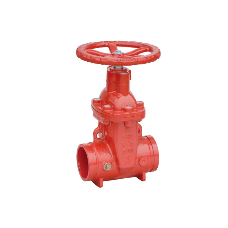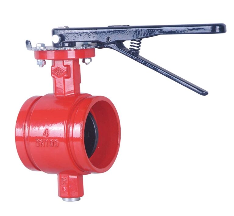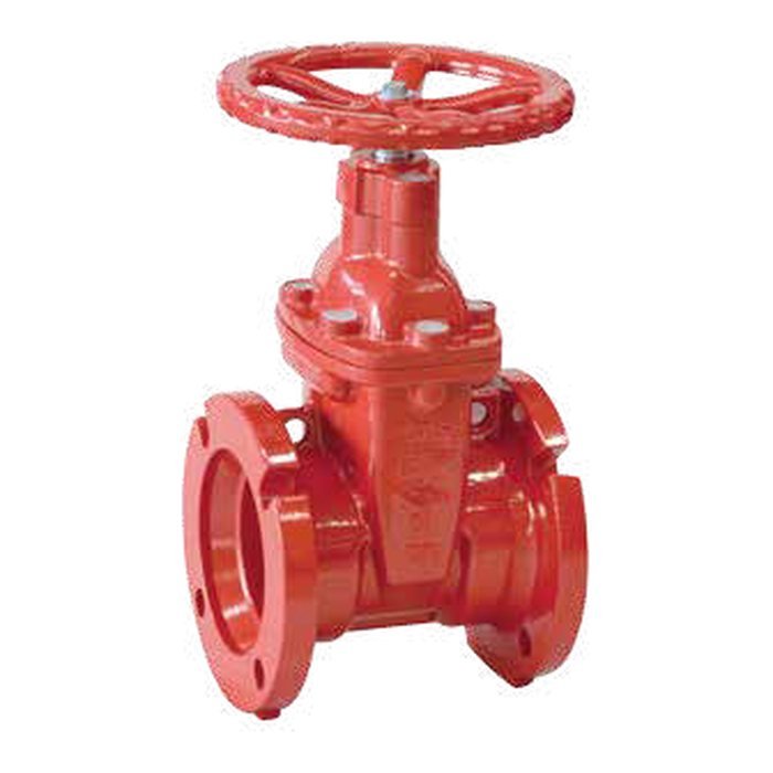
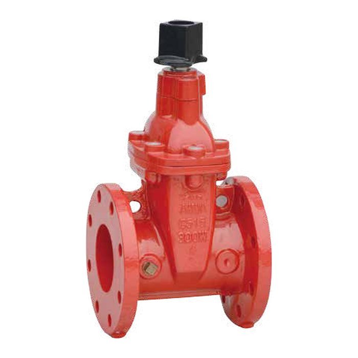
The MECH gate valve nrs flanged with stem cap ul/fm red, model Z45XC, sizes 2″ – 24″ (DN50 – DN600), working pressure 300 PSI (200 / 250 PSI on request), UL / FM approved. A non-rising-stem gate valve suited to limited space and buried mains. This guide explains what it does and how it works, related models, technical data, the critical point in selection and installation, and common mistakes. For more, read the guide OS&Y vs NRS gate valves.
At a glance
- On an NRS (non-rising stem) gate valve the stem turns in place and the gate travels on it inside the body, so the valve height does not change on opening.
- Sizes 2″ – 24″ (DN50 – DN600).
- Working pressure 300 PSI (200 / 250 PSI on request).
- Approvals: UL / FM.
- Connection: Flange ASME B16.1 CL125 / ASME B16.42 CL150.
- Operating temperature: 4 – 60 °C.
NRS gate valve: what it does and how it works
On an NRS (non-rising stem) gate valve the stem turns in place and the gate travels on it inside the body, so the valve height does not change on opening. It therefore suits limited headroom and buried mains.
Because the stem does not show position, an indicating device is used with it: an indicator post mounted on a flange on top of the valve showing “OPEN / SHUT”, or a stem cap operated with a key.
Related models
| Model | Product | Sizes | Pressure | Approvals |
|---|---|---|---|---|
| Z85XC-2 | GATE VALVE NRS GROOVED WITH POST FLANGE UL RED | 4″ – 12″ | 300 psig | UL |
| Z55X | GATE VALVE NRS FLANGE x GROOVE UL RED | 2-1/2″ – 12″ | 300 psig | UL |
| Z05X | GATE VALVE NRS FLANGE x MECHANICAL JOINT UL RED | 3″ – 12″ | 300 psig | UL |
| Z35X | GATE VALVE NRS MECHANICAL JOINT UL RED | 3″ – 12″ | 300 psig | UL |
| Z35XC-2 | GATE VALVE NRS MECHANICAL JOINT WITH POST FLANGE UL/FM RED | 4″ – 12″ (DN100 – DN300) | 300 PSI | UL / FM |
| Z45XC — this product | GATE VALVE NRS FLANGED WITH STEM CAP UL/FM RED | 2″ – 24″ (DN50 – DN600) | 300 PSI | UL / FM |
| Z85X | GATE VALVE NRS GROOVED UL/FM RED | 2″ – 12″ (DN50 – DN300) | 300 PSI | UL / FM |
| Z45XC-2 | GATE VALVE POST FLANGE UL/FM RED | 4″ – 24″ (DN100 – DN600) | 300 PSI | UL / FM |
| Z45X | GATE VALVE NRS H.WHEEL FLANGED UL/FM RED | 2″ – 12″ (DN50 – DN300) | 363 PSI | UL / FM |
Technical data
| Item | Specification |
|---|---|
| Connection ends | Flange ASME B16.1 CL125 / ASME B16.42 CL150 |
| Working pressure | 300 PSI (200 / 250 PSI on request) |
| Temperature | 4 – 60 °C |
| Coating | FBE — ANSI/AWWA C550 |
| Approvals | UL / FM |
| Sizes | 2″ – 24″ (DN50 – DN600) |
Dimensions for every size are in the size table at the top of the page.
Showing the valve position
An NRS valve used as a fire-system control valve needs a means of showing its position, such as an indicator post on buried valves, or supervision per the standard. Choose the model with an indicator-post flange if the valve will be buried.
Caution
Indicator post height and extension rod length are set by the burial depth; send us the depth before ordering.
Installation steps
- Check the end type (flange, groove or mechanical joint) and its standard.
- Install with the stem vertical and upward, restraining mechanical joints with thrust blocks or restraints per the project details.
- For buried valves: fit the indicator post on the flange and set the OPEN/SHUT target to the actual position.
- Cycle fully open and shut and confirm the indicator matches.
Common mistakes
- Burying the valve without an indicator post or other indication.
- Not restraining mechanical joints against thrust.
- An indicator that does not match the actual position after installation.
Files and ordering
On this page: Product page (catalogue), MECH Fire Protection Valves Catalogue (UL/FM), Material Safety Data Sheet (MSDS). Add the product to your request list with size and quantity and we send a quotation, or build a submittal PDF for the consultant. Fu-Mech is the exclusive MECH agent in Saudi Arabia.
Frequently asked questions
When should I choose NRS instead of OS&Y?
Where headroom is limited or the valve is buried in an underground main with an indicator post. See OS&Y vs NRS gate valves.
What is the indicator-post flange for?
It takes an indicator post (vertical or wall) so a buried valve can be operated from above ground and its position seen.
What is the working pressure of model Z45XC?
300 PSI (200 / 250 PSI on request) per the product data. The pressure for each size or listed model is in the size table and datasheet.
What approvals does it carry?
UL / FM per the product data. Check the size and listed model in the approval listings, and see how to verify UL and FM approvals.
What end connection does it have?
Flange ASME B16.1 CL125 / ASME B16.42 CL150. Choose the connection that matches the adjacent pipe and fittings.
References
- ASME B16.42 — Ductile Iron Pipe Flanges and Flanged Fittings: Classes 150 and 300
- ASME B16.1 — Gray Iron Pipe Flanges and Flanged Fittings
- AWWA C550 — Protective Interior Coatings for Valves and Hydrants
- MECH catalogue — Fire fighting valves
This guide is general information to help with selection. Figures come from the product data on this page and the MECH catalogue; final design is by the project’s approved designer to the applicable standards and the project specification.