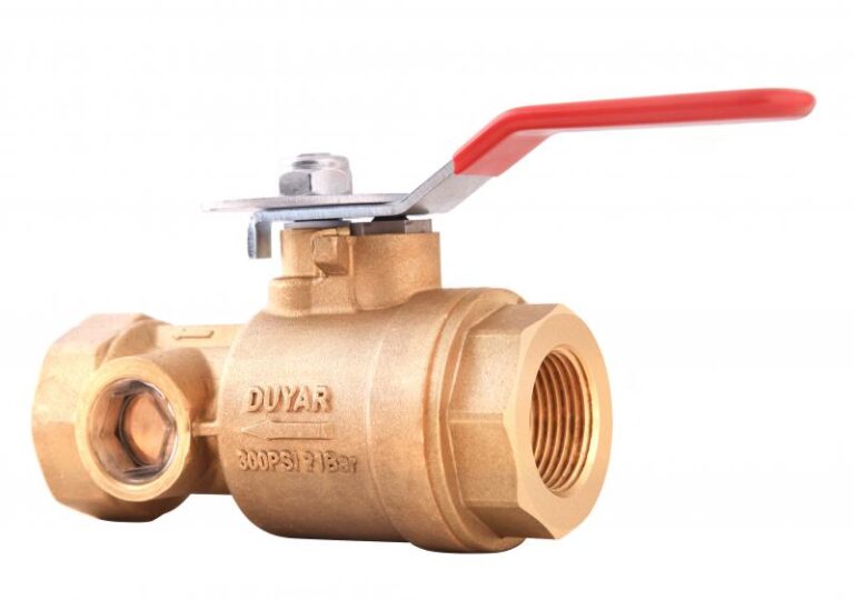
After the flow indicator on each floor sits a small valve with a big role in inspection: the test and drain valve. It simulates one sprinkler operating, to confirm the flow indicator raises the alarm, and it drains the floor for maintenance. This guide explains how it works, where it goes and how it is used.
Key points
- Three positions: off, test, drain.
- The test position passes water through an orifice with a K-factor equal to the smallest sprinkler in the system, simulating one sprinkler opening.
- It is installed after the flow indicator on each floor, with its outlet piped to drain.
- Model Y-4030: sizes 1″–2″, K-5.6 orifice, 300 PSI, to UL 258 and FM 1625.
How it works
The valve is one body with a handle that turns between three positions. In off nothing passes. In test water passes through a calibrated orifice, so the flow equals one open sprinkler, and it shows in a sight glass. In drain the full bore opens to empty the floor quickly.
Why after the flow indicator?
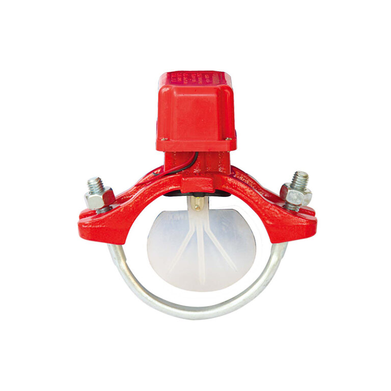
Because the aim is to test the indicator itself: when water flows in the test position, the flow indicator must move and signal the alarm panel within its set retard time. If the valve were before the indicator, no water would pass it. See the flow indicator guide.
Test steps
- Tell alarm monitoring or the building that the test is starting.
- Check the drain line is open and discharges somewhere safe.
- Turn the handle to test and watch the water in the sight glass.
- Record the time until the flow signal reaches the panel.
- Return the handle to off and confirm the alarm has reset.
Warning
The test orifice K-factor must match the smallest sprinkler K-factor on the floor, otherwise the test is easier or harder than reality. Check the orifice when ordering.
Model Y-4030 data
| Item | Value |
|---|---|
| Standard | UL 258 / FM 1625 |
| Ends | Thread ASME B1.20.1 |
| Working pressure | 300 PSI |
| Orifice | K-5.6 |
| Sizes | 1″ – 2″ (DN25 – DN50) |
Details on the product page.
Frequently asked questions
Does the test valve replace the main drain?
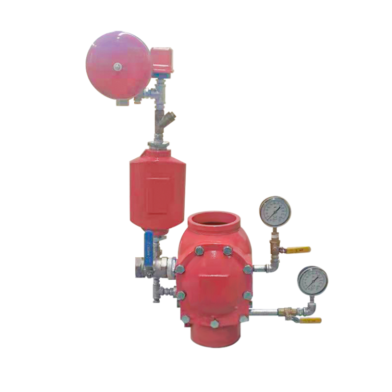
No. The test and drain valve serves the floor; the main drain at the control station empties the system and tests the supply.
How often is the flow indicator tested?
Per the NFPA 25 schedule adopted on the project and the manufacturer’s instructions.
Why does the valve have a sight glass?
To see water passing, confirm the test is working, and confirm the valve is fully shut afterwards.
References
- NFPA 13 — Standard for the Installation of Sprinkler Systems.
- NFPA 25 — Standard for the Inspection, Testing, and Maintenance of Water-Based Fire Protection Systems.
Model data is from the product page; test steps are general practice applied under the project’s procedures.
Part of a complete guide
This article is part of The Complete Guide to Sprinkler Systems in Saudi Arabia: Types, Components and Testing.