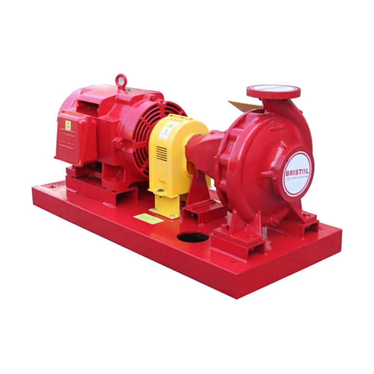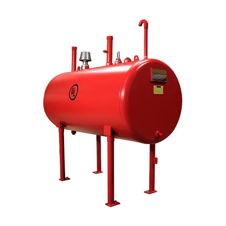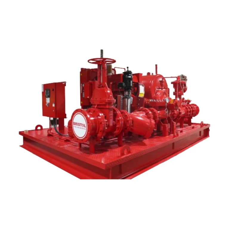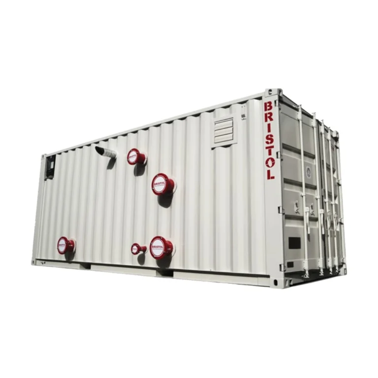
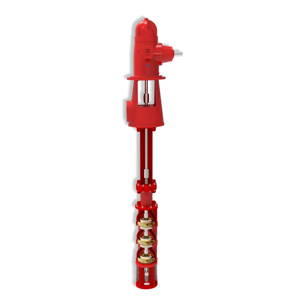
BRISTOL BVP pumps are vertical turbine fire pumps built to NFPA 20. They are used where the water source is below ground level, such as underground tanks and wells: the impellers stay submerged at all times, suspended on the column pipe, so the pump is always primed. They are driven by a vertical electric motor, or by a diesel engine through a right angle gearbox. See the fire water tank connections guide.
In short
- Capacity up to 1500 GPM; head 50 to 210 m.
- Five models: BVP-210 · 250 · 300 · 350 · 400.
- Multi-stage, with impellers always submerged.
- Complies with NFPA 20 and UL 448, with performance and hydrostatic tests.
- Open line shaft: bowl and line-shaft bearings are water lubricated.
- UL Listed (File EX26745) and FM Approved for the ratings in the selection chart.
How it works
The bowl assembly at the bottom holds the impellers; each bowl is a stage adding pressure. Water rises through the column pipe to the discharge head on top of the tank, and the line shaft carries the drive from the motor at the top down to the impellers.
The number of stages sets the pressure, and the column length follows the tank depth. Bowls and suction bell are bolted for easier disassembly, and the balanced impellers are fixed to the shaft with steel locking collets.
Technical data
| Item | Value |
|---|---|
| Capacity | Up to 1500 GPM |
| Head | 50 – 210 m |
| Discharge head | Ductile iron (cast iron in the materials table) |
| Impeller | Bronze or SS304 |
| Line shaft | Stainless steel or duplex steel |
| Column pipe | AISI 1020 / ASTM A106 Gr. B |
| Bowls and suction assembly | ASTM A48 |
| Wear rings | Stainless steel |
| Strainer | Stainless steel |
| Sealing | Packing with flushing |
| Dimensions (mm) | BVP 210: A 170 · C 250 · D 490 — BVP 250: A 208 · C 290 · D 490 — BVP 300: A 240 · C 340 · D 640 — BVP 350: A 310 · C 340 · D 640 — BVP 400: A 352 · C 390 · D 660 |
| Approvals | UL File EX26745; FM per the selection chart |
The critical point: submergence and water level
The impellers must stay submerged at the lowest water level in the tank, so the pump length is set from the tank depth and the lowest operating level. Give the supplier these measurements when ordering.
The selection chart gives the listed and approved pressure for each model, flow and speed; the number of stages changes the pressure.
General design notes on selecting a fire pump
- Rating point: the pump is selected so its rated flow and pressure cover the system demand from the hydraulic calculation.
- Curve shape in NFPA 20: shut-off (no flow) pressure does not exceed 140% of rated pressure, and at 150% of rated flow the pressure is not less than 65% of rated.
- Horizontal pumps need positive suction (water source above the pump). Where the source is below the pump, a vertical turbine pump is used.
- A jockey pump makes up small leaks and holds system pressure, so the main pump starts only on real demand.
- Driver type (electric or diesel) and the number of standby pumps depend on the reliability of the power supply and the authority’s requirements.
- Shut-off pressure plus suction pressure must not exceed the pressure rating of system components; otherwise reselect or manage the pressure per the standard.
General engineering notes
These points are general principles from NFPA 20, NFPA 25 and common design practice, not from the BRISTOL catalogue. Final pump selection is made by the project’s approved designer from the hydraulic calculation and the requirements of the authority having jurisdiction.
Installation steps
- Check the tank top opening, the mounting base, the tank depth and the lowest water level.
- Lower the bowl assembly and strainer, then fit the column pipe and line shaft sections one by one.
- Fix the discharge head to the base (a sole plate is optional on request).
- Fit the vertical motor or right angle gear, and set the impeller clearance per the factory instructions.
- Connect the discharge line and controller, then run the acceptance test.
Common mistakes
- Ordering without stating the tank depth and lowest water level.
- A strainer too close to the tank floor, drawing in sediment.
- Using a horizontal pump with a tank below it instead of a vertical turbine.
- Skipping the impeller clearance adjustment after installation.
Inspection and maintenance
Per NFPA 25, the fire pump is run periodically at no flow to confirm readiness, and an annual flow test measures the curve points (no flow, rated flow and 150% of rated) against the factory curve.
Inspection, testing and maintenance are the owner’s responsibility per NFPA 25, preferably by a qualified company. Notify the owner, the monitoring station and everyone affected before any test.
Files and ordering
The BRISTOL fire pumps catalogue (with the selection charts and dimensions) is in the files section of this page. For a quotation, state the required flow (GPM), required pressure (psi or bar), driver type (electric or diesel), and whether UL or FM is required, plus the tank depth and lowest water level.
How to order
Use the “Build your order” section on this page: add every model and quantity, then send the whole order by email or WhatsApp. It reaches us as a tidy PDF request sheet and we contact you with the quotation.
FAQ
When do I need a vertical turbine pump?
When the water level is below the pump, such as an underground tank beneath the pump room. Horizontal pumps need positive suction.
Can it run on a diesel engine?
Yes, through a right angle gearbox that turns the horizontal engine drive onto the vertical shaft.
References
- BRISTOL Fire Pumps Issue 6.0 — Datasheet (attached)
- NFPA 20 — Standard for the Installation of Stationary Pumps for Fire Protection
- UL 448 — Centrifugal Stationary Pumps for Fire-Protection Service
- NFPA 25 — Inspection, Testing and Maintenance of Water-Based Fire Protection Systems
This page is general information to help with selection and ordering, taken from the attached BRISTOL datasheet. Final design is set by the project’s approved designer; the project specification, the consultant’s drawings and the latest datasheet revision govern.