Pressure reducing valves and pressure relief valves look alike, but they do completely different jobs. A pressure reducing valve holds the downstream pressure at a set value however the upstream pressure varies. A pressure relief valve opens to discharge water when pressure exceeds a set limit, protecting the system from overpressure. This guide explains the difference, where each is used, and what to watch for in fire systems.
Key points
- A reducing valve controls pressure downstream; a relief valve caps the maximum pressure in the line.
- In tall buildings reducing valves lower the pressure on lower floors.
- Valves in fire systems must be listed for that service; the MECH models here are for water networks.
- The designer sets the set point, and it must be checked at commissioning.
Pressure reducing valves
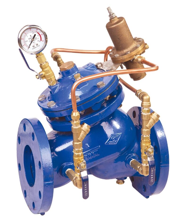
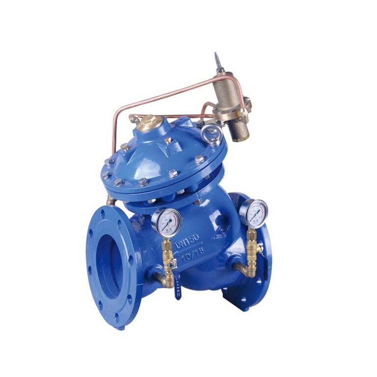
The valve senses downstream pressure and throttles or opens to hold it at the set point. On larger valves this is usually done through a small pilot circuit that controls the main valve.
Typical uses: supplying lower floors in tall buildings, protecting fixtures and pipework from high mains pressure, and steadying pressure on branches of water networks.
Pressure relief valves
The valve stays closed in normal operation and opens when pressure exceeds the set point, discharging some water, then closes again as pressure falls. For fire pump systems NFPA 20 requires a relief valve in specific cases, including where the pump’s churn pressure could exceed the pressure rating of system components.
Comparison
| Item | Pressure reducing | Pressure relief |
|---|---|---|
| Function | Steady pressure downstream | Maximum pressure in the line |
| Normal state | Partly open, modulating continuously | Closed, opens above the limit |
| Location | In the line ahead of the zone it protects | On a branch discharging to a safe outlet |
| Typical use | Tall buildings and network branches | Protecting systems and pumps from overpressure |
MECH models
| Model | Type | Ends | Sizes | Pressure |
|---|---|---|---|---|
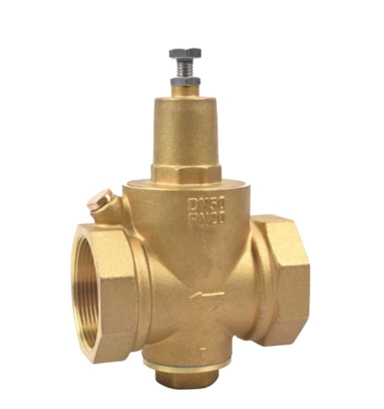
| SK720X | Pressure reducing | Flanged BS EN 1092-2 | 2″ – 24″ | PN10 / PN16 / PN25 |
| SK730X | Pressure relief | Flanged BS EN 1092-2 | 2″ – 12″ | PN25 |
| Y11X-702A | Brass pressure reducing | Threaded ISO 228 | 1/2″ – 2″ | — |
For fire systems
Pressure reducing valves in sprinkler and hose systems must be listed for fire protection service. Do not use water-network models in a fire system without checking the approval and the consultant’s acceptance.
Installation and commissioning
- Fit a Y-strainer ahead of a reducing valve to protect the pilot circuit from debris.
- Fit pressure gauges before and after the valve to set and monitor it.
- Provide isolation valves for maintenance, and a bypass where the design calls for one.
- Set the required value at commissioning and test it under real flow.
- Route the relief valve outlet to a safe, visible discharge point.
Frequently asked questions
Can a pressure reducing valve act as a relief valve?
No. A reducing valve controls downstream pressure and does not discharge excess pressure from the line. Overpressure protection needs a relief valve.
Why fit a strainer ahead of a reducing valve?
The pilot circuit has small passages that debris can block; the strainer protects them and keeps control accurate.
What do PN16 and PN25 mean?
They are nominal pressure classes in European standards; the number is roughly the nominal pressure in bar.
References
- NFPA 13 — Standard for the Installation of Sprinkler Systems.
- NFPA 14 — Installation of Standpipe and Hose Systems.
- NFPA 20 — Installation of Stationary Pumps for Fire Protection.
- EN 1092-2 — Flanges and their joints: Cast iron flanges.
- MECH data for models SK720X, SK730X and Y11X-702A on the product pages below.
This guide is for technical awareness and does not replace the manufacturer’s data sheet or the requirements of the project’s approved designer.