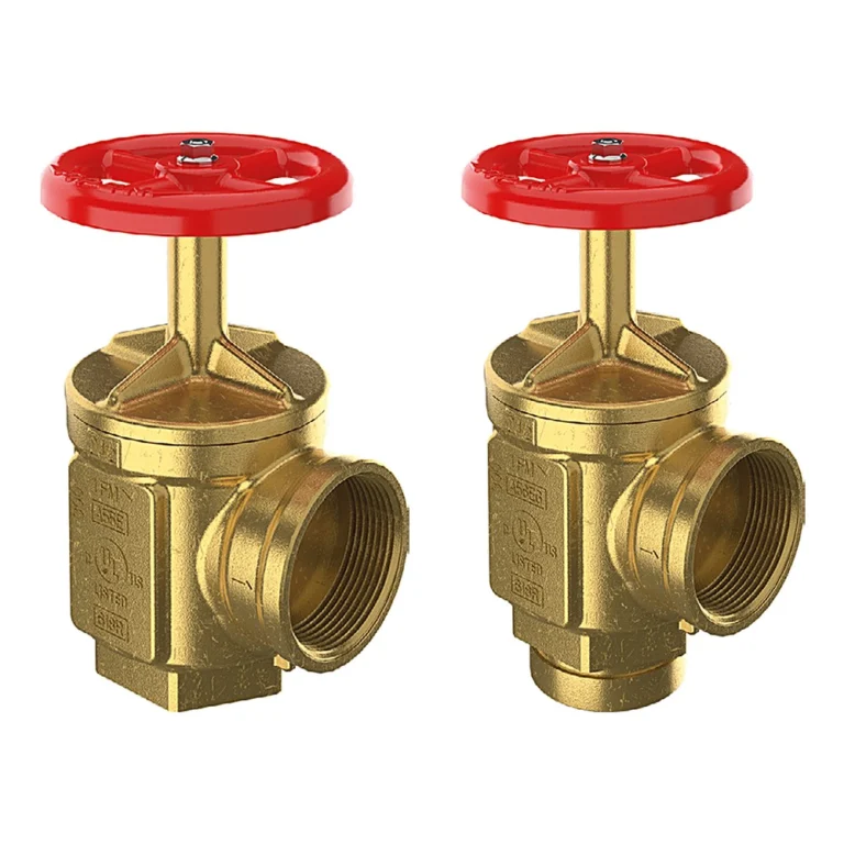
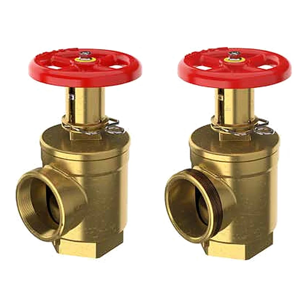
The GIACOMINI A155 and A156 (datasheet 0692EN) are angle hose valves that restrict outlet pressure through an adjustable flow restriction, for hose connections on standpipe systems with working pressure up to 300 psi. They reduce pressure under flowing (residual) conditions only, not at static. If full flow is needed, the restriction can be overridden by pulling the spring clip. See the pressure reducing vs relief valve comparison.
In short
- Two models: A155 (NPT-F × NPT-F) and A156 (NPT-F × male hose thread).
- Sizes: 1-1/2″ and 2-1/2″.
- Pressure: 175 psi as a pressure restricting valve; 300 psi maximum rated.
- Field settings: 1 to 15 for 1-1/2″ and 1 to 20 for 2-1/2″, then full open (F.O.).
- Spring clip to override the restriction when full flow is required.
- Intended for Class III standpipe systems per the datasheet.
How the valve restricts pressure
The setting collar on the stem limits how far the valve opens. Each setting number has a fixed flow coefficient Cv: a lower number means a smaller opening and a larger inlet-to-outlet pressure drop at the same flow.
The pressure drop follows ΔP = (GPM / Cv)², with ΔP the inlet-to-outlet difference in psi. The Cv table is in the technical data below, and the flow curves are in the datasheet.
Because the restriction depends on flow, outlet pressure returns to inlet pressure when flow stops. That is the difference from pressure reducing valves, which regulate both static and residual pressure.
Related items
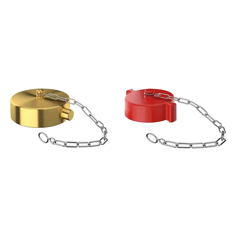
- A80 cap and chain for the A156 outlet.
- A55E / A56E standard hose valves for floors needing no restriction.
Technical data
| Item | Value |
|---|---|
| Models | A155 · A156 |
| Sizes | 1-1/2″ × 1-1/2″ · 2-1/2″ × 2-1/2″ |
| Rated as pressure restricting valve | 175 psi |
| Max. rated pressure | 300 psi |
| Body and bonnet | Forged brass CuZn40Pb2 to EN 12165 CW617N (similar to ASTM B124 C37700) |
| Stem | Brass EN 12164 CW614N |
| Handwheel | Red painted aluminium |
| Cv for 1-1/2″ (setting: value) | 1: 4.40 · 2: 6.20 · 3: 6.95 · 4: 7.60 · 5: 7.78 · 6: 8.03 · 7: 10.09 · 8: 12.70 · 9: 13.91 · 10: 16.63 · 15: 19.67 · F.O.: 28.00 |
| Cv for 2-1/2″ (setting: value) | 1: 13.9 · 2: 19.6 · 3: 24.2 · 4: 25.5 · 5: 28.1 · 6: 30.05 · 7: 30.9 · 8: 34.08 · 9: 35.78 · 10: 37.6 · 11: 38.4 · 12: 39.45 · 13: 40.45 · 14: 41.8 · 15: 43.39 · 16: 46.8 · 17: 51.2 · 18: 58.36 · 19: 65.6 · 20: 73.32 · F.O.: 125 |
| A155 1-1/2″ dimensions | A 4-1/32″ · B 6-1/2″ closed / 7-19/32″ open · C 2-5/32″ · D 1-7/8″ |
| A155 2-1/2″ dimensions | A 5-1/8″ · B 8-29/32″ closed / 10-19/32″ open · C 3-5/32″ · D 2-5/8″ |
| A156 1-1/2″ dimensions | A 4-1/32″ · B 6-1/2″ closed / 7-19/32″ open · C 2-1/4″ · D 1-7/8″ |
| A156 2-1/2″ dimensions | A 5-1/8″ · B 8-29/32″ closed / 10-19/32″ open · C 3″ · D 2-5/8″ |
| Approvals | UL Listed (A156: EX3504, 175 psi), ULC 175 psi, FM 300 psi (1521/1522) |
The critical point: set from the calculation, and restriction only while flowing
The valve must not be set to give less than the minimum pressure required by NFPA 14 while flowing 250 GPM for 2-1/2″ and 100 GPM for 1-1/2″. The minimum residual pressure is 100 psi at the most remote 2-1/2″ connection and 65 psi at the most remote 1-1/2″ station; other pressures must be authorised by the fire department.
The pressures in the curves are at the valve outlet. Friction loss between outlet and nozzle is calculated by qualified personnel, and some nozzles do not work properly at 100 psi, so consult the fire authority on the pressure its equipment needs.
The curves refer to the conditions tested at the Giacomini test station. If the local code or the designer needs other conditions, request alternate curves from the factory.
General design notes for standpipe systems
- System classes in NFPA 14: Class I has 2-1/2″ outlets for fire fighters, Class II has 1-1/2″ hose stations for occupants, and Class III combines both.
- Required residual pressure at the hydraulically most remote outlet: 100 psi for a 2-1/2″ connection and 65 psi for a 1-1/2″ station, as the Giacomini datasheet quotes from NFPA 14.
- Where pressure at a hose outlet exceeds 175 psi an appropriate pressure regulating device is used, as the FM Approval Guide states for hose valves.
- The hose outlet thread (NH/NST or other) must match the local fire department’s hose thread; confirm before ordering.
General engineering notes
These points are general principles from the NFPA standards named and common design practice, not from the GIACOMINI datasheet. The final decision rests with the project’s approved designer per the adopted edition of the standard and the authority having jurisdiction.
Installation steps
- Install pipe unions or rubber-gasketed fittings immediately upstream and downstream of the valve to permit easy replacement.
- Connect the valve to the piping using the hexagon at the bottom of the body, without deforming the bonnet.
- Select the setting number from the proper graph for the size, from the hydraulic calculation.
- Close the valve hand-tight, then loosen the set screw in the collar.
- Rotate the indicator cap until the top of the collar reaches the selected setting number, then tighten the set screw.
- Pressure test for tightness. To override the restriction, pull the spring clip.
Common mistakes
- Using the same setting on every floor although inlet pressure differs floor to floor.
- Treating the valve as reducing static pressure, when it only restricts while flowing.
- Operating the valve with a torque bar. Excess torque damages the seat and stem.
- Trying to replace internal parts. The valve is not designed for replacement parts and is replaced whole if it fails to perform.
Inspection and maintenance
Per the datasheet: inspect annually for damage or corrosion. Every two to three years drain the system, open all valves fully, lubricate the stem and check the seat for debris. If the valve leaks, open the test valve to flush it. Replacement is recommended after ten years.
Per NFPA 25, pressure regulating devices on hose connections are flow tested periodically to confirm the outlet pressure.
Inspection, testing and maintenance are the owner’s responsibility per NFPA 25 and the authority having jurisdiction, preferably by a qualified company. Notify the owner, the monitoring station and everyone affected before any test.
Files and ordering
The GIACOMINI datasheet 0692EN (with the flow curves) and the UL and FM listings are in the files section of this page. When ordering, state the model, size, outlet thread and, if you want suggested settings, the inlet pressure and required flow per floor.
How to order
Use the “Build your order” section on this page: add every model and quantity, then send the whole order by email or WhatsApp. It reaches us as a tidy PDF request sheet and we contact you with the quotation.
FAQ
Pressure restricting vs pressure reducing?
A restricting valve lowers pressure only while flowing, by narrowing the opening. A reducing valve regulates both static and residual pressure.
Can a fire fighter get full flow?
Yes, pulling the spring clip overrides the restriction and the valve opens fully.
How do I pick the setting?
From inlet pressure, required flow and required outlet pressure, using the datasheet curves or the Cv table, approved by the project designer.
Does the UL listing cover both models?
The attached UL listing (EX3504) is for the A156; the datasheet shows UL, ULC and FM marks for both. The attached FM approval covers the A155 and A156.
References
- GIACOMINI 0692EN — Datasheet (attached)
- NFPA 14 — Standard for the Installation of Standpipe and Hose Systems
- NFPA 25 — Inspection, Testing and Maintenance of Water-Based Fire Protection Systems
This page is general information to help with selection and ordering, taken from the attached GIACOMINI datasheet. Final design is set by the project’s approved designer; the project specification, the consultant’s drawings and the latest datasheet revision govern.