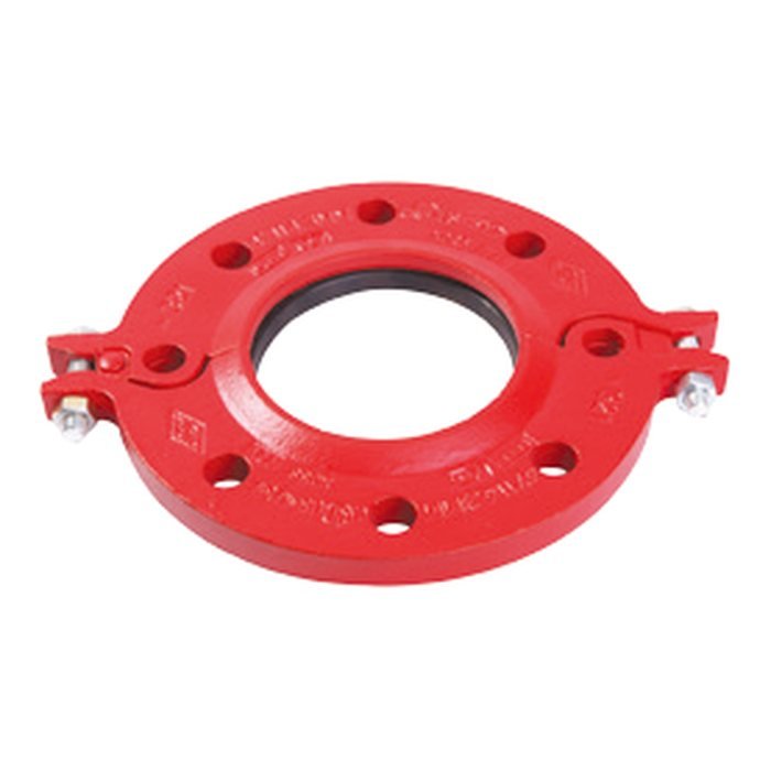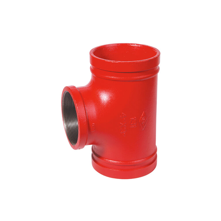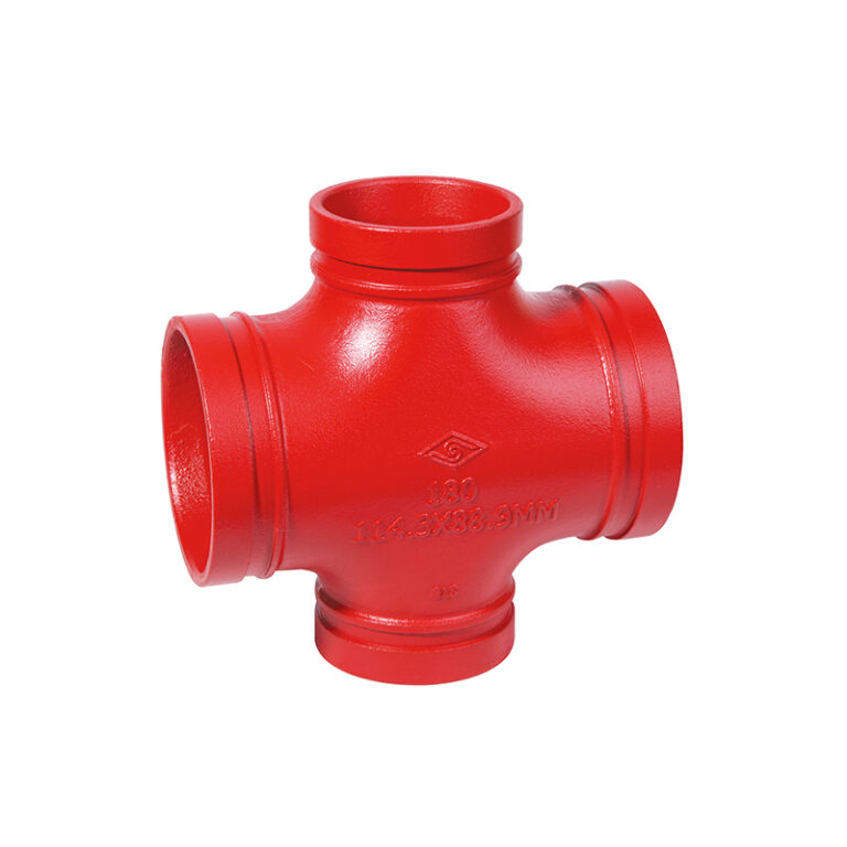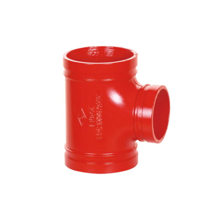

The MECH grooved red cross tee(thd), model 181, in ductile iron, sizes 2-1/2″ × 2″ – 8″ × 3″ (DN65×50 – DN200×80), working pressure up to 300 PSI, UL / FM approved depending on size. This guide explains what it does and how it works, compares it with related models, and covers technical data, the critical point in selection and installation, and common mistakes. For more, read the technical library guide.
At a glance
- A reducing tee takes a branch smaller than the main line directly, replacing an equal tee plus reducer.
- Sizes 2-1/2″ × 2″ – 8″ × 3″ (DN65×50 – DN200×80) — working pressure up to 300 PSI.
- Approvals: UL / FM (vary by size).
- Material Ductile iron ASTM A536 Gr. 65-45-12.
- Designed to ASTM F1548, AWWA C606, ISO 6182-12.
What is a grooved reducing tee and how does it work?
A reducing tee takes a branch smaller than the main line directly, replacing an equal tee plus reducer. A reducing cross takes two opposite branches smaller than the main. The branch is grooved or female-threaded depending on the model.
A threaded branch suits direct connection to small threaded pipe or fittings such as sprinkler lines, drains or gauges.
Models in the same family
| Model | Item | Sizes | Max pressure | Approvals |
|---|---|---|---|---|
| 181RX | MECH GROOVED REDUCING CROSS (THD) | 6″ × 3″ | 300 PSI | UL / FM |
| 180RX | MECH GROOVED REDUCING CROSS | 6″ × 4″ – 8″ × 6″ | 300 PSI | UL / FM |
| 130D | MECH GROOVED REDUCING TEE | 4″ × 3″ × 1″ – 6″ × 3″ × 1″ | 300 PSI | UL / FM |
| 130C | MECH GROOVED REDUCING TEE | 4″ × 3″ × 1″ – 6″ × 3″ × 1″ | 300 PSI | UL / FM |
| 181 — this product | MECH GROOVED RED CROSS TEE(THD) | 2-1/2″ × 2″ – 8″ × 3″ | 300 PSI | UL / FM |
| 180R | MECH GROOVED RED CROSS TEE | 2-1/2″ × 2″ – 8″ × 6″ | 500 PSI | UL / FM |
| 131RX | MECH GROOVED REDUCING TEE (THD) | 2″ × 1″ – 8″ × 4″ | 300 PSI | UL / FM |
| 131R | MECH GROOVED RED TEE (THD) | 2″ × 1″ – 8″ × 4″ | 500 PSI | UL / FM |
| 130RX | MECH GROOVED RED TEE (GRVD) | 3″ × 2-1/2″ – 12″ × 10″ | 300 PSI | UL / FM |
| 130R | MECH GROOVED REDUCER TEE | 2-1/2″ × 2-1/2″ × 3″ – 24″ × 20″ | 500 PSI | UL / FM / VdS / LPCB |
Technical data
| Item | Specification |
|---|---|
| Design standard | ASTM F1548, AWWA C606, ISO 6182-12 |
| Material | Ductile iron ASTM A536 Gr. 65-45-12 |
| Coating | Electrophoretic (std.) — epoxy / hot-dip galvanized optional |
| Sizes | 2-1/2″ × 2″ – 8″ × 3″ (DN65×50 – DN200×80) |
| Approvals | Sizes | Working pressure |
|---|---|---|
| UL / FM | 2-1/2″ × 2″ – 6″ × 2″ | 300 PSI |
| Not stated in the table | 3″ × 1-1/4″ – 8″ × 3″ | 300 PSI |
Full dimensions for every size (bolts and more) are in the size table at the top of the page.
End sizes and branch type
A reducing tee is ordered by its sizes (run × run × branch), and the branch type (grooved or threaded) and thread must match what connects to it.
Caution
Check the size table; the size you need may be in another model of the same family.
Installation steps
- Check that the pipe ends are grooved to the right dimensions to AWWA C606 (roll or cut groove) and are free of burrs, rust and dirt.
- Inspect the gasket and lubricate its outside and lips with the lubricant recommended in the MECH catalogue; never use petroleum-based products with an EPDM gasket.
- Fit the gasket over one pipe end, bring the other end or the fitting into place, and slide the gasket so it is centred between the two grooves.
- Place both housing halves over the gasket so their keys engage the grooves on both sides.
- Hand-tighten the nuts first, making sure each oval-neck bolt sits in its hole, then tighten alternately and evenly to the torque in the MECH installation manual — never exceed it.
The fitting joins with grooved couplings; how the joint is finished (even pad gap or pads meeting) follows the coupling type in the MECH manual.
Full details and bolt torques are in the MECH installation manual among the files on this page.
Common mistakes
- Letting the gasket lip overhang the pipe end or protrude into a groove, so the gasket is not centred on the joint.
- Exceeding the specified bolt torque, which can damage the bolt or the joint.
- Grooves that do not meet AWWA C606 dimensions, or pipe ends that are not square.
- Tightening the nuts on one side only, so the housing tilts and the key does not seat in the groove.
- Using petroleum-based lubricant that damages the EPDM gasket.
Files and ordering
On this page: Product page (catalogue), MECH Grooved Fittings & Couplings Catalogue, Installation & operation manual, Material Safety Data Sheet (MSDS). Add the product to your request list with size and quantity and we send a quotation, or build a submittal PDF for the consultant. Fu-Mech is the exclusive MECH agent in Saudi Arabia.
Frequently asked questions
When should I choose a threaded branch over a grooved one?
When the branch connects directly to small threaded pipe or fittings. For larger branches or grooved networks choose a grooved branch. See the guide grooved tees, crosses and reducers.
What is the maximum working pressure of model 181?
Up to 300 PSI. The pressure for each size is in the size table.
Is model 181 UL / FM approved?
Yes. Approvals by size: UL / FM for 2-1/2″ × 2″ – 6″ × 2″; — for 3″ × 1-1/4″ – 8″ × 3″. See the size table on this page and the guide how to verify UL and FM approvals.
What is the gasket material, and does it suit all fluids?
Gasket type and suitable services are given in the MECH catalogue.
Does it suit roll-grooved and cut-grooved pipe?
Grooves are to AWWA C606, rolled or cut; what matters is correct groove dimensions. The difference is explained in the guide roll grooving vs cut grooving.
References
- ASTM F1548 — Standard Specification for Performance of Fittings for Use with Gasketed Mechanical Couplings Used in Piping Applications
- AWWA C606 — Grooved and Shouldered Joints
- ISO 6182-12 — Fire protection — Automatic sprinkler systems — Requirements and test methods for grooved-end components for steel pipe systems
- ASTM A536 — Standard Specification for Ductile Iron Castings
- UL 213 — Rubber Gasketed Fittings for Fire-Protection Service
- FM 1920 — Approval Standard for Pipe Couplings and Fittings for Fire Protection Systems
- MECH catalogue — Grooved Fittings & Couplings — and installation manual
This guide is general information to help with selection. Figures come from the product data on this page and the MECH catalogue; final design is by the project’s approved designer to NFPA 13 and the project specification.