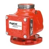
The TYCO Model AV-1-300 is an alarm check valve for wet pipe sprinkler systems. It stays closed while the system is at rest; when there is a steady flow into the system equal to one or more sprinklers, it opens and automatically actuates electric and/or hydraulic alarms. It works at water pressures from 20 to 300 psi and installs vertically or horizontally. For how system types compare, see wet, dry, pre-action and deluge systems compared.
In short
- Sizes: 2-1/2″, 4″, 6″ and 8″ (DN65 – DN200).
- Working pressure: 20 – 300 psi (1.4 – 20.7 bar).
- Ends: groove × groove, flange × groove, flange × flange (flange × flange not offered in 2-1/2″).
- Vertical installation for all sizes; horizontal for 4″, 6″ and 8″ only.
- Approvals: UL, C-UL and FM.
How the alarm check valve works
When the system is first filled, water enters until supply and system pressure equalise and the spring closes the waterway clapper on the seat ring. In this set position the central groove in the seat ring is sealed, so no water reaches the alarm line.
When a sprinkler operates and water flows steadily, the clapper opens and water passes into the seat-ring groove, out of the alarm port and to the restriction assembly. Once flow through the inlet restriction (5.6 mm) exceeds the outlet drain restriction (3.2 mm), the alarm line fills and the water motor alarm and/or pressure alarm switch actuate, for as long as the clapper stays open.
Transient supply surges do not cause false alarms: the bypass check valve passes slow and small pressure rises into the system without opening the clapper, and any water that enters the alarm line drains away automatically.
Related items
- Model RC-1 retard chamber (datasheet TFP920): ordered separately and required where supply pressure varies, to prevent false alarms.
- Valve trim: pressure gauges, bypass check valve, main drain valve and alarm test valve. Available vertical closed drain (standard), vertical open drain, or horizontal closed drain for 4″ to 8″.
- Alarm vent trim: must be installed when a water motor alarm is not used.
Technical data
| Item | Value |
|---|---|
| Sizes | 2-1/2″, 4″, 6″, 8″ (DN65, DN100, DN150, DN200) |
| Working pressure | 20 – 300 psi (1.4 – 20.7 bar) |
| End connections | Groove × groove, flange × groove, flange × flange |
| Flange drilling | ANSI B16.42 Class 150, ISO 7005-2 PN10 / PN16, JIS B 2210 10K, AS 2129 Table E |
| Materials | Ductile-iron body and cover, bronze seat ring, stainless clapper in 2-1/2″ and ductile iron in larger sizes, EPDM facing |
| Weight (groove × groove) | 10.0 / 17.2 / 26.3 / 46.3 kg for 2-1/2″ / 4″ / 6″ / 8″ |
| Approvals | UL, C-UL and FM |
The critical point: trapped air in the system
The datasheet warns that a large volume of trapped air (for example in a peaked-roof gridded system) can cause an intermittent alarm: the clapper opens, then closes before the alarm is established.
The datasheet’s remedy: a vent connection (which can double as the end-of-line inspector’s test connection) from the top of a cross main or the end of a branch line, at the point most remote from the valve and at the highest level, and filling the system slowly per the setting procedure.
Installation requirements
- Install the valve in a readily visible, accessible location, preferably with the main drain outlet where alarm-line drain water can be seen.
- Vertical installations flow upward; horizontal installations have the drain connection pointing down.
- Trim the valve per the applicable figure in the datasheet, applying pipe-thread sealant sparingly to male threads only.
- Plug unused alarm connections; install the alarm vent trim if no water motor alarm is used.
- Install the bypass check valve with its arrow up and the drain check valve with its arrow toward the drain.
- Provide safe disposal for alarm-line and system drainage, and plan for the large volumes released when draining or flow testing.
- Keep the wet pipe system at 4°C minimum.
Common mistakes
- Leaving out the RC-1 retard chamber where supply pressure varies, leading to false alarms.
- Filling the system fast without venting, trapping air and causing intermittent alarms.
- Installing the bypass or drain check valve against its arrow.
- Not notifying the owner and the fire department or monitoring station before filling or testing, even though filling the system operates the alarms.
- Not cleaning the 1/2″ and 3/4″ trim strainers after each alarm operation.
Inspection and maintenance
The datasheet recommends inspection at least quarterly by a qualified inspection service: open the inspector’s test connection (or the alarm test valve, if acceptable to the authority having jurisdiction), confirm the water motor alarm or pressure switch operates within the required time, that water leaves the alarm-line drain at a rate consistent with the 3.2 mm orifice, and that it stops after closing. The datasheet also covers clearing alarm-line drain leakage and the handhole-cover bolt torque for each size.
Files and ordering
TYCO datasheet TFP910 and the UL and FM certificates are in the files section of this page. When ordering, state the size, end connections, flange drilling standard, trim type (vertical or horizontal, closed or open drain) and whether an RC-1 retard chamber is needed.
How to order
Use the “Build your order” section on this page: add every model, size and quantity, then send the whole order by email or WhatsApp. It reaches us as a tidy PDF request sheet and we contact you with the quotation.
FAQ
Do I need the RC-1 retard chamber?
It is required where the water supply pressure varies, such as public mains, to prevent false alarms from pressure fluctuation. With a steady supply, the designer decides.
Can it be installed horizontally?
Yes for 4″, 6″ and 8″ only, with the drain connection pointing down and horizontal trim. The 2-1/2″ size installs vertically.
What causes an intermittent alarm?
Usually a large volume of trapped air in the system. Vent from the most remote, highest point and fill slowly.
Is it suitable for dry systems?
No. Per the datasheet it is for wet pipe systems only; dry systems use dedicated dry pipe valves.
How often is it inspected?
The datasheet recommends at least quarterly by a qualified inspection service, in addition to NFPA 25 and the authority having jurisdiction.
References
- TYCO TFP910 — Model AV-1-300 alarm check valve datasheet (attached)
- TYCO TFP920 — Model RC-1 retard chamber
- NFPA 13 — Standard for the Installation of Sprinkler Systems
- NFPA 25 — Inspection, Testing and Maintenance of Water-Based Fire Protection Systems
This page is general information to help with selection and ordering, taken from the attached TYCO datasheet. Final design is set by the project’s approved designer; the project specification, the consultant’s drawings and the latest datasheet revision govern.