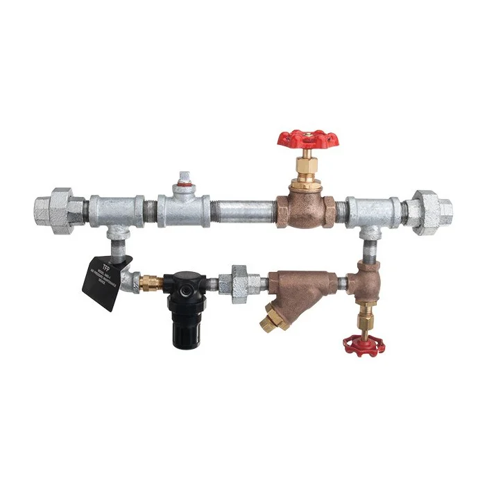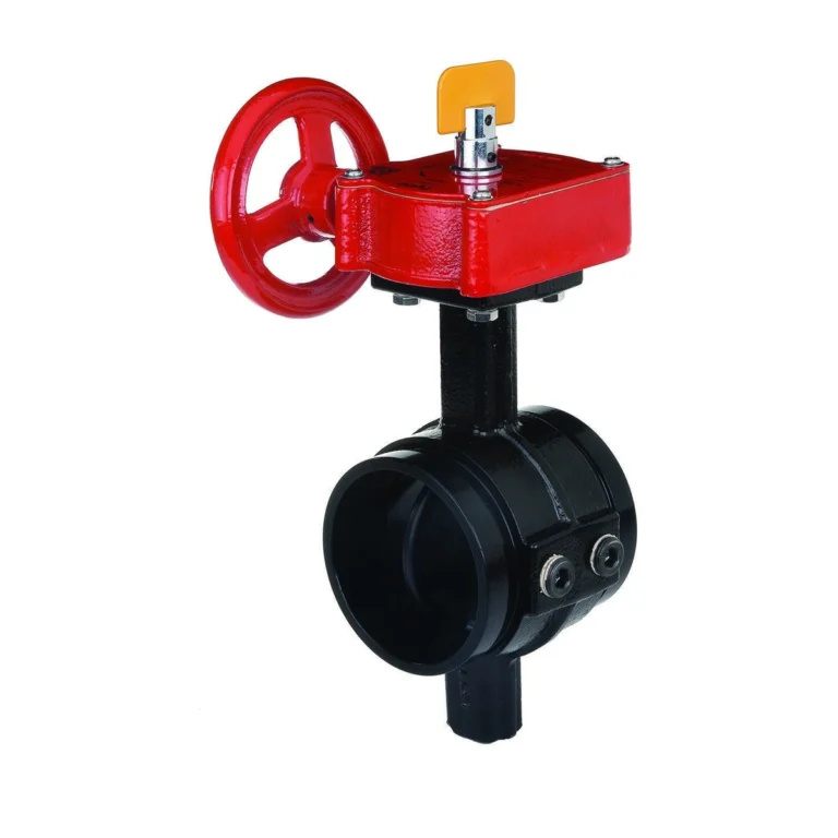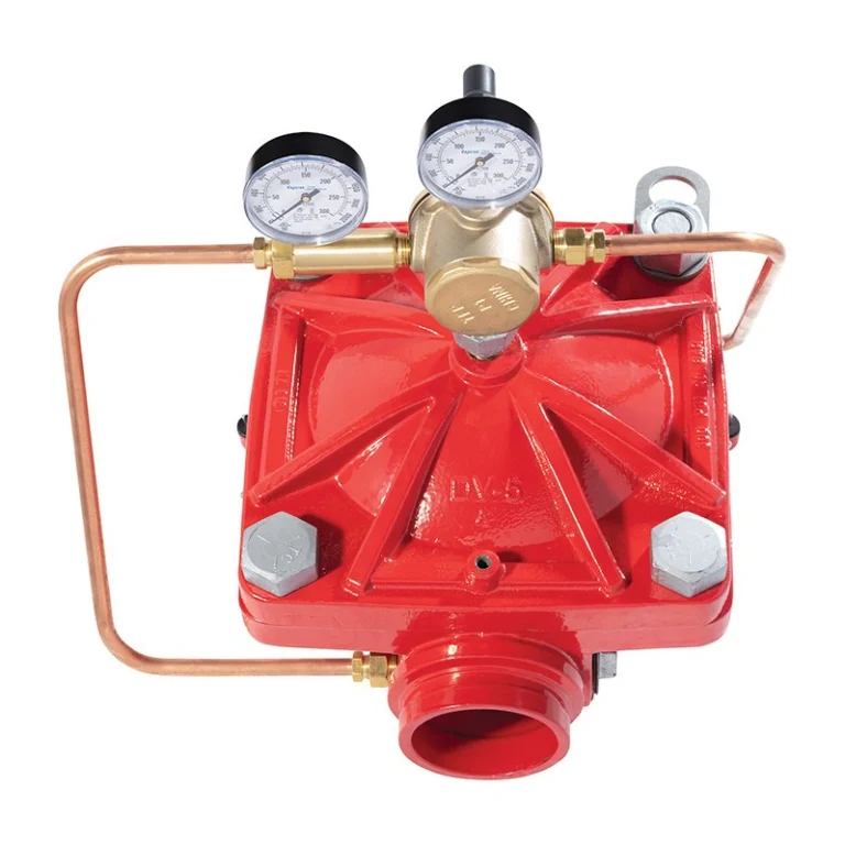
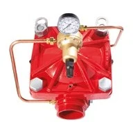
The TYCO RV-1A is a factory-assembled, fully trimmed pilot-operated pressure relief valve, 2″ to 8″. It is typically used to relieve excess pressure automatically in fire pump systems, holding a relatively constant pressure at the pump discharge as demand changes. Its central component is the DV-5A valve. See the guide to types of fire fighting valves.
In short
- Factory set about 175 psi (12.1 bar); field set 100 – 250 psi (UL) or 30 – 250 psi (FM).
- Recommended maximum flow: 2″ 250 gpm, 3″ 500, 4″ 1000, 6″ 2500, 8″ 5000 gpm.
- One-piece, one-moving-part diaphragm, epoxy coated inside and out, serviceable in line.
- Installs in any orientation provided gauges are readable from a safe position and the valve can be inspected per NFPA 25.
How the valve works
It is installed on a tee after the fire pump and before the system check valve. When pressure exceeds the set point it opens, passing excess flow back to the tank and holding the required pressure.
If system demand stops completely the valve stays fully open, relieving 100% of pump capacity; the check valve closes to isolate the system and the pump shuts off safely.
Technical data
| Item | Value |
|---|---|
| Type | Pilot-operated diaphragm pressure relief |
| Sizes | 2″ – 8″ (DN50 – DN200) |
| End connections | Grooved or ANSI flange; PN flange for EMEA and APAC |
| Relief set pressure | UL 100 – 250 psi · FM 30 – 250 psi |
| Reference | NFPA 20 |
| Approvals | UL · FM |
The critical point: corrosion protection
In corrosive and outdoor locations protect the valve from moisture and chemicals, coat exposed steel threads to prevent galvanic corrosion, or build a rain-resistant roof or enclosure over the valve and trim.
Installation steps
- Install the valve with the flow arrow on the diaphragm cover pointing in the direction of flow, and flush the pipe lines of chips and scale before installing.
- Do not lift the valve by its trim, and take care not to damage the trim during installation.
- Install on a tee after the pump and before the check valve, discharging to the tank per NFPA 20.
- Field-set the relief pressure within the approved range.
Common mistakes
- Choosing a size beyond its recommended flow.
- Lifting the valve by its trim.
- Leaving exposed threads unprotected outdoors.
Inspection and maintenance
Before closing a main control valve for maintenance, obtain permission from the proper authorities and notify everyone affected. The owner is responsible for inspection, testing and maintenance to NFPA 25 and the authority having jurisdiction; any impairment must be corrected immediately.
Use the troubleshooting table in the datasheet (Table C) for any problem.
Files and ordering
TYCO datasheet TFP1586 and the available approval certificates are in the files section of this page. When ordering, state the size, end connections and required relief pressure. The datasheet lists the part numbers (P/N).
How to order
Use the “Build your order” section on this page: add every model and quantity, then send the whole order by email or WhatsApp. It reaches us as a tidy PDF request sheet and we contact you with the quotation.
FAQ
Why a relief valve with a fire pump?
To protect the system from overpressure when demand drops, and the pump when demand stops completely, per NFPA 20.
Can it be installed vertically?
Yes, in any orientation provided gauges are readable from a safe position and it can be inspected.
What is the factory setting?
About 175 psi, field set to the design.
References
- TYCO TFP1586 — Datasheet (attached)
- NFPA 20 — Installation of Stationary Fire Pumps
- NFPA 25 — Inspection, Testing and Maintenance of Water-Based Fire Protection Systems
This page is general information to help with selection and ordering, taken from the attached TYCO datasheet. Final design is set by the project’s approved designer; the project specification, the consultant’s drawings and the latest datasheet revision govern.