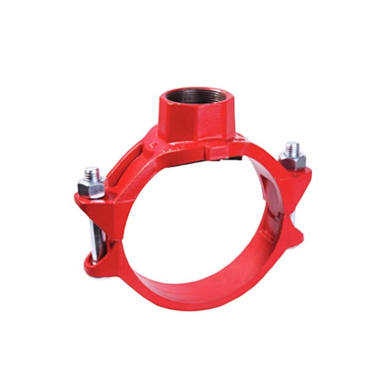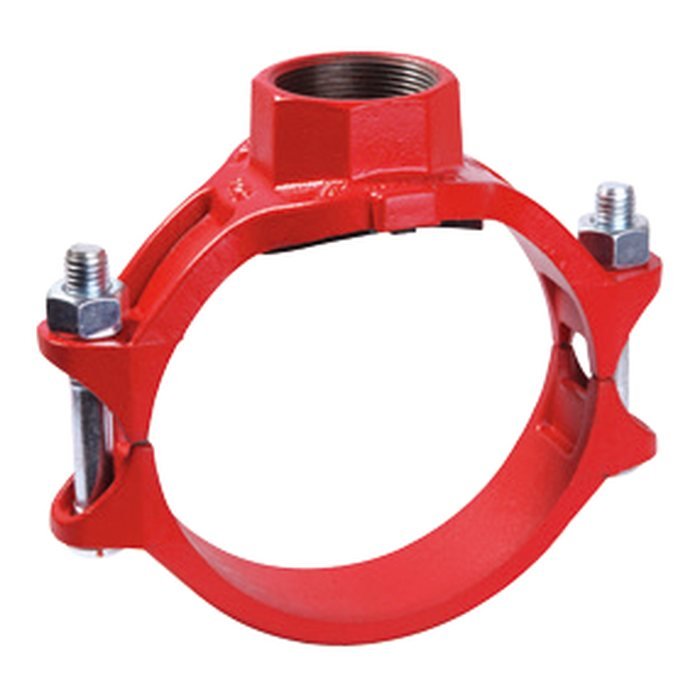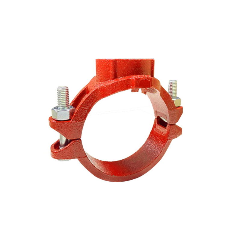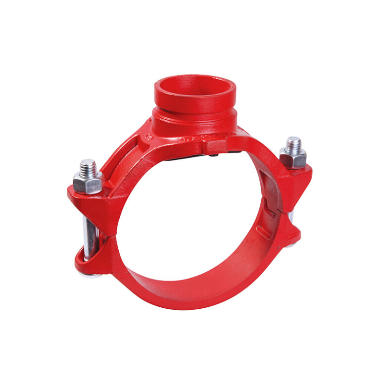
A mechanical tee is the quickest way to take a branch off an existing pipe in sprinkler and fire water systems: a hole is drilled in the pipe wall, the tee is clamped over it with two bolts, and you have a side outlet ready to connect — without cutting or welding the pipe. This guide explains how it works, when it is the right choice, how to pick the model, and what makes for a leak-free installation.
Key points
- Adds a branch to a main without cutting the pipe, with no welding and no extra couplings.
- The outlet is threaded or grooved depending on the model; a U-bolt version suits small outlets.
- The hole diameter is the single most important dimension and must match the model’s size table exactly.
- Pressure rating and approvals (UL / FM / VdS) vary by size, so the product table is always the reference.
How does a mechanical tee work?
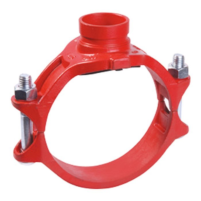
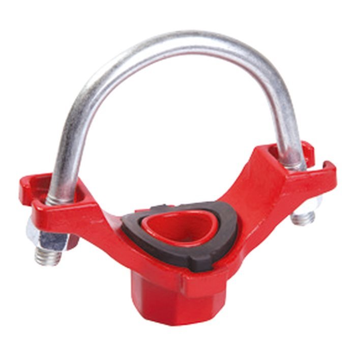
The tee consists of two halves that clamp around the pipe: the upper housing carries the outlet and the gasket seat, and the lower housing closes underneath, with a bolt on each side. On some models a U-bolt replaces the lower housing.
The rubber gasket surrounds the hole and has a locating collar that sits in the hole itself, which positions the tee and stops it from shifting. Tightening the bolts compresses the gasket against the outside of the pipe, and line pressure increases the seal.
When to choose it over a grooved tee or a welded outlet
A standard grooved tee is a full fitting: the line has to be cut, both ends grooved and two couplings fitted. A welded outlet needs welders and, on many sites, a hot-work permit. A mechanical tee wins when the branch is smaller than the main, or when a branch is added to an existing line.
| Item | Mechanical tee | Grooved tee | Welded outlet |
|---|---|---|---|
| Cut the main | No | Yes | No |
| Hot work | No | No | Yes |
| Parts | One fitting | Tee + two couplings | Outlet + weld |
| Adding to an existing line | Easy | Part of the line must be removed | Possible after draining and weld preparation |
| Best for | Branches smaller than the main | Equal or near-equal branches | As the project specification requires |
MECH models and ranges
| Model | Outlet | Sizes | Max. working pressure |
|---|---|---|---|
| 3J | Threaded | 1″ × 3/8″ – 10″ × 4″ | up to 400 PSI |
| 3JS | Threaded (light duty) | 3″ × 1/2″ – 8″ × 4″ | up to 400 PSI |
| 3JX | Threaded | 2-1/2″ × 1″ – 6″ × 2-1/2″ | 300 PSI |
| 3G | Grooved | 2″ × 1-1/4″ – 10″ × 4″ | up to 400 PSI |
| 3GS | Grooved (light duty) | 3″ × 1″ – 8″ × 4″ | up to 365 PSI |
| 3L | Threaded, U-bolt | 1-1/4″ × 1/2″ – 6″ × 1-1/2″ | up to 300 PSI |
All models are cast in ductile iron ASTM A536 Gr. 65-45-12 with a Grade “E” EPDM gasket for sprinkler and water service.
How to choose
Choose a threaded outlet when the branch connects to threaded pipe, a sprinkler or a small fitting directly, and a grooved outlet when the branch continues in grooved pipe and couplings. Then confirm that the size is listed with the approval the project specification requires.
Hole diameter: the dimension that matters most
Every size has a specified hole diameter in the product table (the Hole diameter column). It is not a minor detail:
- Hole too small: the gasket collar cannot seat, the tee sits incorrectly and flow to the branch is reduced.
- Hole too large: the gasket does not fully cover the edge of the hole — a direct cause of leaks.
Caution
Use a hole saw of exactly the diameter in the table, and do not round between metric and imperial sizes.
Installation steps
- Depressurise and drain the line, and mark the branch position on the top or side of the pipe as designed.
- Drill the hole to the diameter given for that size, keeping the drill square to the pipe axis.
- Deburr the hole inside and out, and clean the pipe surface around it of rust, flaking paint and dirt.
- Inspect the gasket for type and condition, then place the upper housing so that the gasket collar enters the hole.
- Fit the lower housing or U-bolt and tighten the bolts alternately and evenly as the manufacturer instructs.
- Pressure-test the system to the project requirements before putting it into service.
Common mistakes to avoid
- Drilling an approximate hole size or using the wrong cutter.
- Leaving swarf inside the pipe, where water carries it to the sprinklers.
- Tightening one bolt fully before the other, so the tee tilts and the gasket is compressed unevenly.
- Selecting a model without checking pressure and approval for the exact size.
Frequently asked questions
Can a mechanical tee be installed on a pressurised line?
Standard installation is on a depressurised line. Connecting to a live line under pressure (hot tapping) needs special equipment and procedures outside the scope of this guide.
Is it acceptable in NFPA 13 sprinkler systems?
NFPA 13 permits fittings listed for fire protection service within the limits of their listing. Check that the required size carries the right approval (UL or FM) in the product table, and that the consultant accepts it.
How do the light-duty models (3JS and 3GS) differ?
They cover a narrower size range, with working pressures up to 400 and 365 PSI respectively. Compare pressure and approval for the required size in each model’s table before choosing.
Does it suit any type of pipe?
That depends on pipe type, wall thickness and outside diameter. Check the model’s data sheet for approved pipe types and confirm the pipe OD on your project.
References
- NFPA 13 — Standard for the Installation of Sprinkler Systems.
- UL 213 — Rubber Gasketed Fittings for Fire-Protection Service.
- FM Class 1920 — Pipe Couplings and Fittings for Fire Protection Systems.
- ISO 6182-12 — Grooved-end components for steel pipe systems.
- ASTM A536 — Ductile Iron Castings.
- MECH size tables for models 3J, 3JS, 3JX, 3G, 3GS and 3L on the product pages below.
This guide is for technical awareness and does not replace the manufacturer’s data sheet or the requirements of the project’s approved designer.