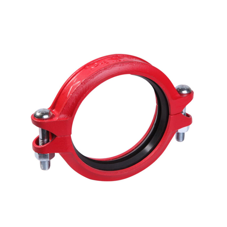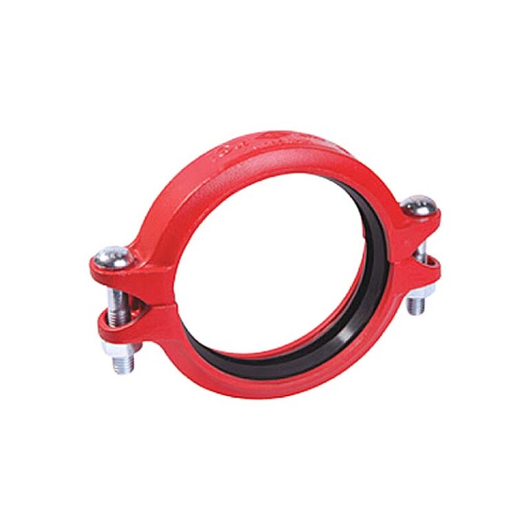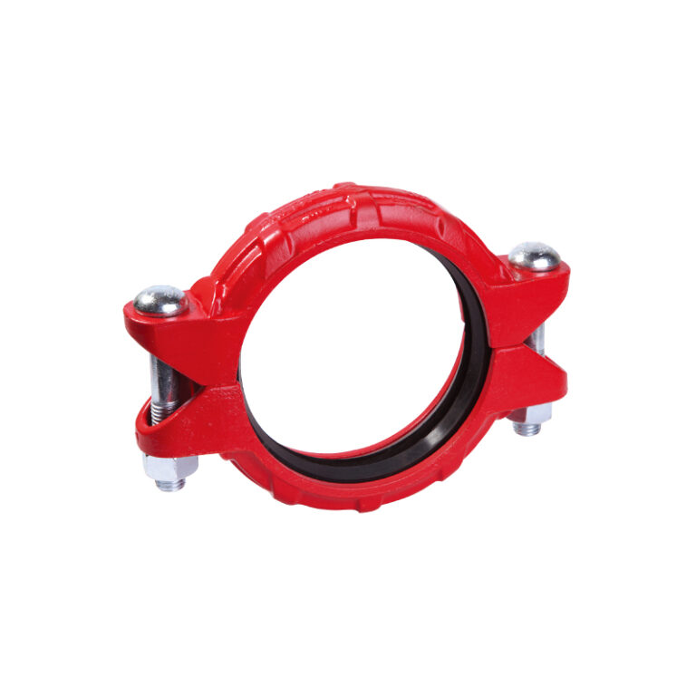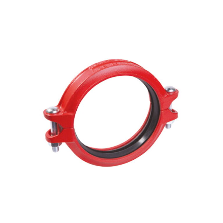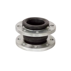
A grooved piping system joins pipes, fittings and valves with a groove formed near the pipe end and a bolted coupling, without welding or threading. It has spread across fire protection, HVAC and water networks because it is faster to install, easier to maintain and needs no hot-work permit. This complete guide gathers what a designer and contractor need: how the joint works, how to choose between rigid and flexible, grooved fittings and valves, installation and inspection, with links to a guide for each part.
Key points
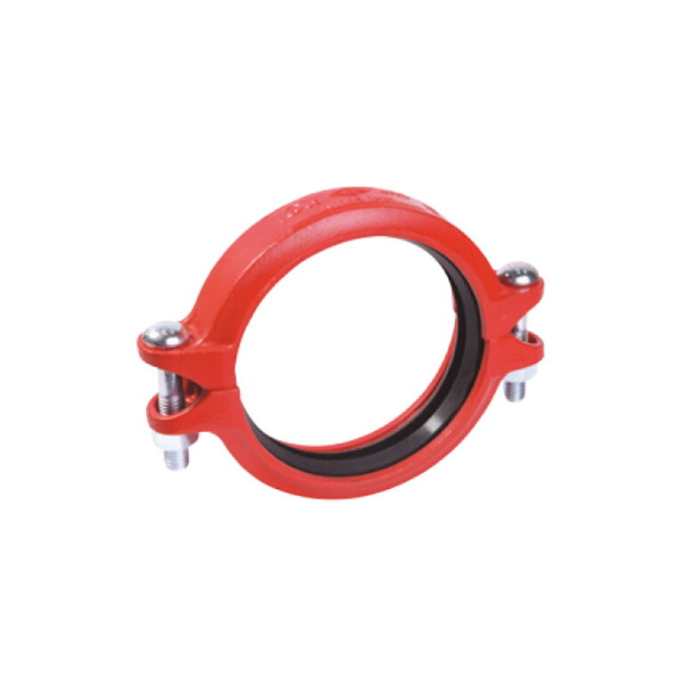
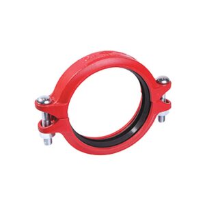
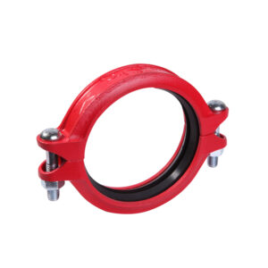
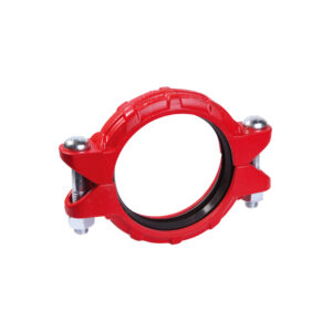
- The joint has three parts: a two-piece housing, a rubber gasket, and bolts and nuts.
- A rigid coupling behaves like a weld; a flexible one allows limited deflection and expansion.
- MECH grooved fittings are ductile iron to ASTM A536, couplings are made to ASTM F1476, and working pressure reaches 500 PSI in some models and sizes, per the model table.
- Most grooved joint failures come from installation: an incorrect groove, an unlubricated gasket, or unevenly tightened bolts.
How a grooved joint works
A circumferential groove is formed near each pipe end. The gasket is placed over both ends, then the two-piece housing is fitted so that its keys engage the grooves, and the bolts are tightened. The housing holds the pipes mechanically and stops them separating under pressure; the gasket seals the water, and its shape is designed so that water pressure tightens the seal.
Grooved versus welded and threaded
- Speed: a joint is made in minutes, with no welding or hot-work permit.
- Maintenance: removing a coupling lets a valve or fitting come out without cutting the pipe.
- Flexibility: flexible couplings absorb thermal expansion, vibration and building settlement.
- Cautions: correct couplings and supports are needed, because flexible joints do not resist every load the way a weld does.
Details in grooved vs welded piping.
Rigid or flexible coupling?
A rigid coupling clamps the pipe ends so they cannot move, and is used where the line must stay fixed: in pump rooms, around valves, and on lines that need fewer supports. A flexible coupling allows limited angular deflection and axial movement, and is used to absorb expansion and vibration and at building expansion joints. See the detailed comparison.
MECH grooved models
| Model | Type | Sizes |
|---|---|---|
| 1G | Rigid coupling | 1″ – 32″ |
| 1GX | Rigid coupling (slim) | 1-1/4″ – 10″ |
| 1N | Flexible coupling | 1″ – 24″ |
| 1NX | Flexible coupling (slim) | 2″ – 10″ |
| 1NH | Heavy-duty flexible coupling | 2″ – 18″ |
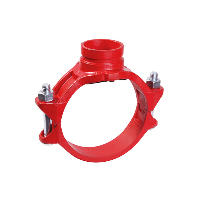
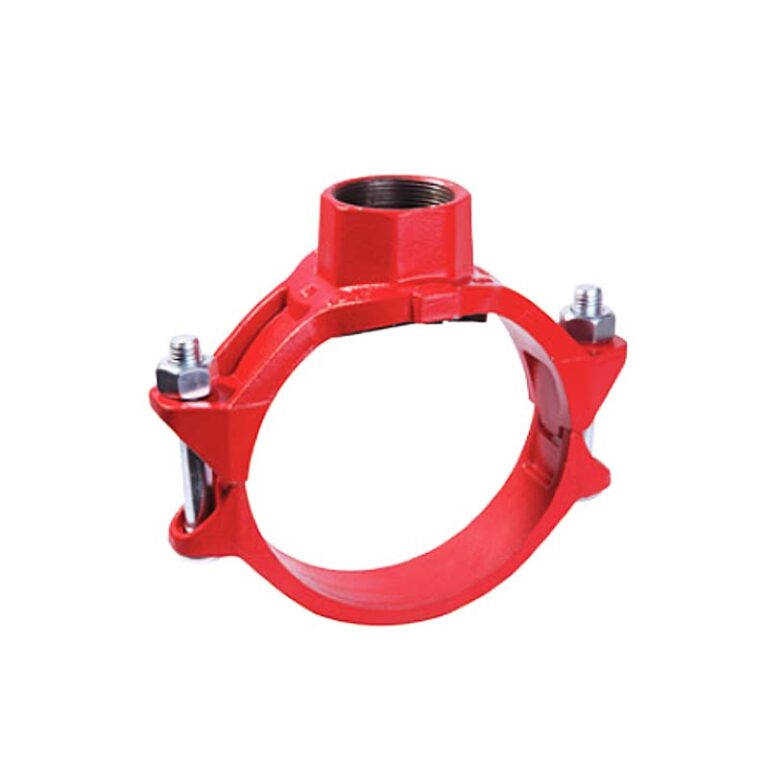
| 3G / 3J | Mechanical tee (grooved / threaded outlet) | 1″ – 10″ (run) |
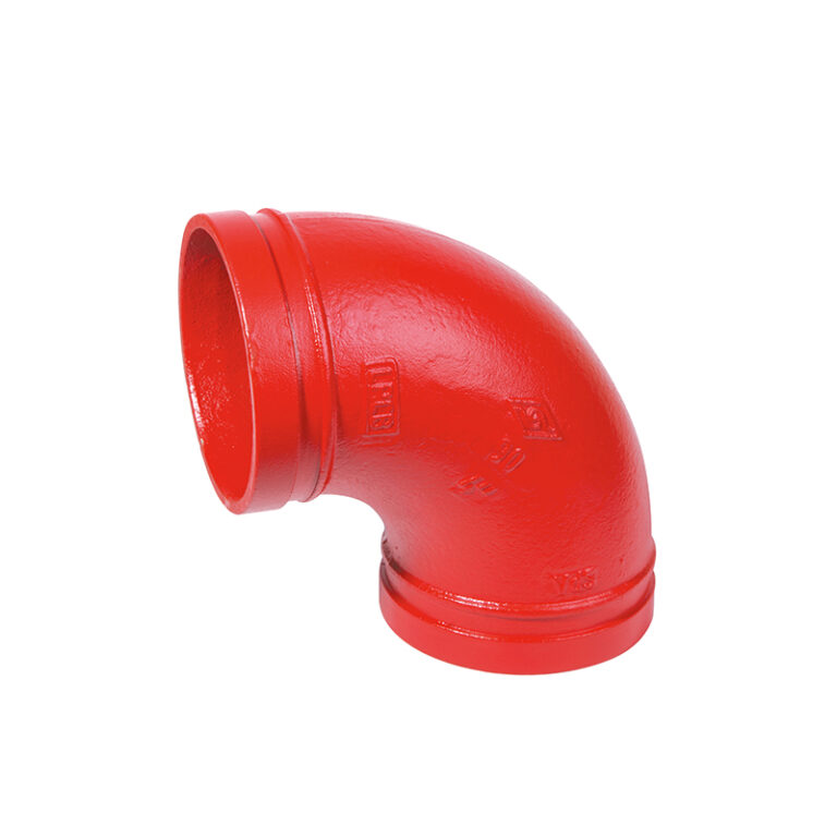
| 90 | 90° elbow | 1″ – 24″ |
| 321 | Grooved flange PN16 | 1-1/2″ – 24″ |
| D381X | Grooved butterfly valve UL/FM | 2″ – 12″ |
Each model has a table with the outside diameter, working pressure, end load and approvals for every size. Fitting guides: elbows, tees and reducers, mechanical tee, end cap.
The critical detail: the groove and the outside diameter
Warning
The coupling is chosen on the pipe’s actual outside diameter, and the groove dimensions (depth, width and distance from the end) must match the manufacturer’s table. A groove that is too shallow or too deep weakens the joint’s pressure resistance. See the pipe size and outside diameter chart and roll vs cut grooving.
Installation steps
- Inspect the pipe ends: clean, free of burrs, rust or weld bead in the gasket seating area, and the groove matching the table.
- Confirm the gasket grade suits the service (EPDM for water and fire protection).
- Coat the gasket with the lubricant approved by the manufacturer and fit it over one pipe end.
- Bring the ends together and slide the gasket so it is centred over the gap without entering the groove.
- Fit the housing halves so the keys engage both grooves, then the bolts and nuts.
- Tighten the nuts alternately until the housing pads meet, or as the model instructions specify.
- Check visually that the keys sit fully in both grooves on each side.
Common mistakes
- Fitting the gasket without lubricant, so it rolls or is pinched between the housing halves.
- Fully tightening one nut before the other, so the housing tilts and does not seat in the groove.
- Choosing the coupling by nominal size without confirming the outside diameter.
- Using flexible couplings everywhere without enough supports, so the line moves under pressure.
Frequently asked questions
Are grooved joints accepted in fire protection systems?
Yes, when the couplings and fittings are UL Listed or FM Approved for the use, size and pressure required, and installed to the manufacturer’s instructions.
Can a gasket be reused after a joint is taken apart?
It is better to fit a new gasket on reassembly, especially in fire protection systems.
What is the working pressure of grooved couplings?
It varies with model, size and outside diameter. In the MECH 1N coupling, for example, it reaches 500 PSI in many sizes and is lower in some; the correct figure is in the model table.
References
- ASTM F1476 — Performance of Gasketed Mechanical Couplings for Use in Piping Applications.
- ASTM F1548 — Performance of Fittings for Use with Gasketed Mechanical Couplings.
- AWWA C606 — Grooved and Shouldered Joints.
- ISO 6182-12 — Fire protection — Automatic sprinkler systems — Grooved-end components.
- NFPA 13 — Standard for the Installation of Sprinkler Systems.
Installation steps are general practice; each model’s manufacturer instructions are the reference, and design is the responsibility of the project’s approved designer.