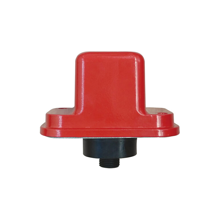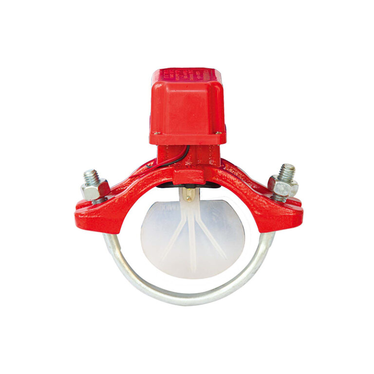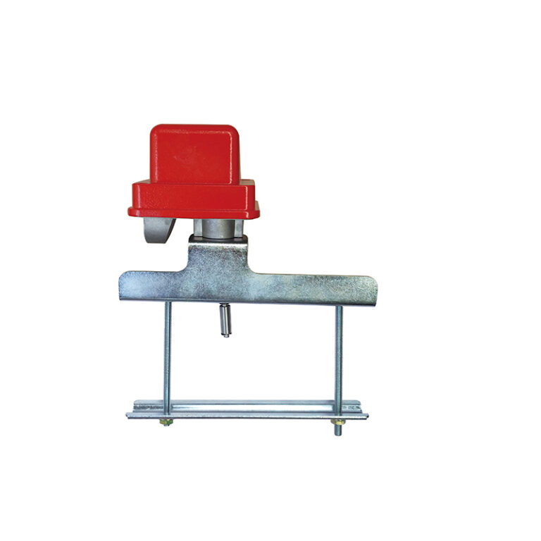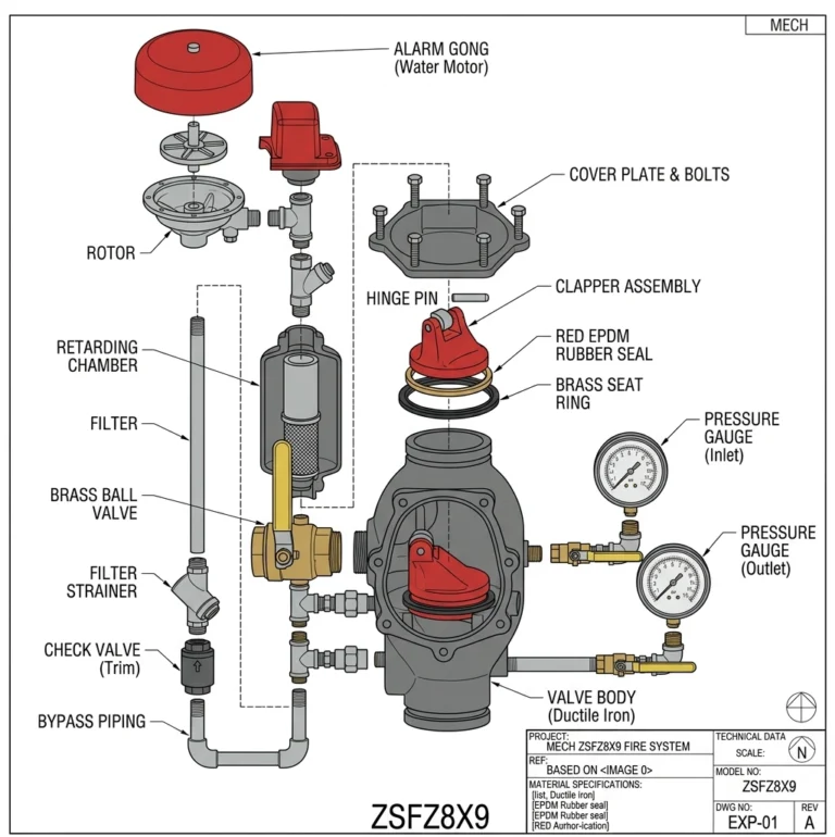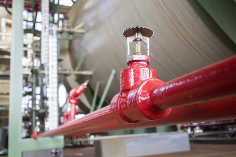
A water flow indicator is the device that tells the alarm panel that water has started flowing in the sprinkler system — that a sprinkler has opened or there is a large leak. It is usually installed on each floor or zone, so it pinpoints where the event is. This guide explains how it works, how to install it correctly, and the MECH model specification.
Key points
- A vane inside the pipe moves with the flow and closes an electrical contact that sends the signal.
- It is mounted on the pipe through a hole of the diameter given in the table.
- The retard timer on these devices reduces false alarms from pressure surges.
- The MECH ZSJZYS is UL / FM approved from 2″ to 8″; the 10″ size is not UL / FM listed.
How does it work?
A flexible vane enters the pipe through a hole in its top and sits roughly across the flow. When water flows at a sufficient rate the vane bends with it, moving a lever that operates a switch in the device housing. The switch signals the alarm panel, which sounds the alarm and identifies the zone.
MECH ZSJZYS specification
| Item | Value |
|---|---|
| Sizes | 2″ – 10″ (DN50 – DN250) |
| Working pressure | 363 / 300 PSI (200 / 250 PSI on request) |
| Minimum flow for alarm | 4 – 10 gpm |
| Electrical rating | 125/250 VAC 5A, 24/30 VDC 3A |
| Temperature | 0 – 68 °C |
| Coating | FBE — ANSI/AWWA C550 |
| Approval | UL / FM / CSFM; 10″ not UL / FM listed |
Correct installation
- Choose a location on straight pipe, clear of elbows, valves and branches by the distance the data sheet specifies.
- Drill the hole in the top of the pipe to the diameter in the product table for that size, and remove all swarf in and around it.
- Insert the vane carefully and make sure the arrow on the device matches the flow direction.
- Tighten the mounting bolts evenly as the data sheet instructs.
- Wire the device to the alarm panel and set the retard timer as the designer requires.
- Test it by opening the zone inspector’s test valve and confirming the signal arrives.
Caution
Swarf or drilling debris inside the pipe can snag the vane or travel to the sprinklers. Clean the hole thoroughly, and do not fit the device on dry pipe or a dry system unless the data sheet allows it.
Why a retard timer?
Sudden pressure changes, such as a pump starting or supply surges, can move the vane momentarily with no real flow. The timer holds the signal until flow continues for a set time, reducing false alarms. The designer sets the delay according to the code and the authority’s requirements.
Frequently asked questions
How does a flow indicator differ from an alarm valve?
The alarm valve in the valve room alarms for the whole system; flow indicators on branches or floors identify the zone where water is flowing.
Does a flow indicator work in dry systems?
Vane-type indicators are generally for wet systems. Check the device’s data sheet before any other use.
How is the indicator tested?
By opening the zone’s inspector’s test valve to simulate one sprinkler flowing and confirming the signal arrives after the set delay.
References
- NFPA 13 — Standard for the Installation of Sprinkler Systems.
- NFPA 72 — National Fire Alarm and Signaling Code.
- UL 346 — Waterflow Indicators for Fire Protective Signaling Systems.
- MECH data for model ZSJZYS on the product page below.
This guide is for technical awareness and does not replace the manufacturer’s data sheet or the requirements of the project’s approved designer.